Home/
Registry/
Ford/
Bronco/
1992-1996/
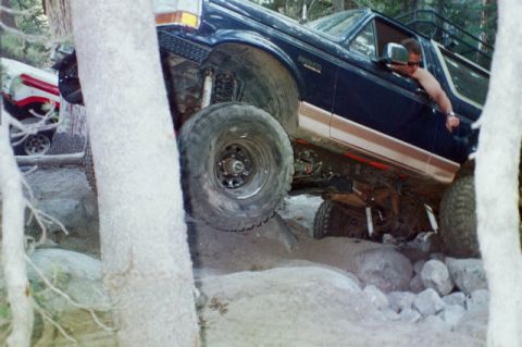
1994 Ford Bronco/
Photo
supermotors.net/registry/media/1128758
Ford EEC/EFI Wiring Diagram 1987-1988 - Fuel Pump Relay, Injectors, TFI Module

Reference · 1992-1996 BroncoAll 411 wiring diagrams


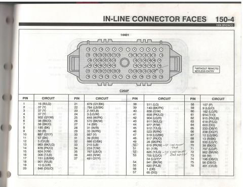
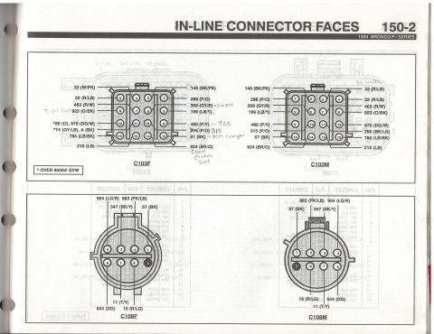
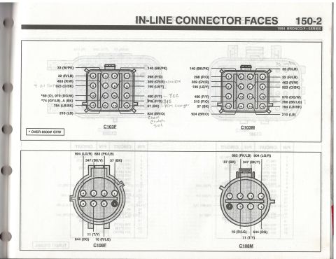
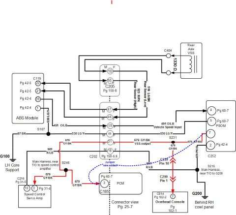
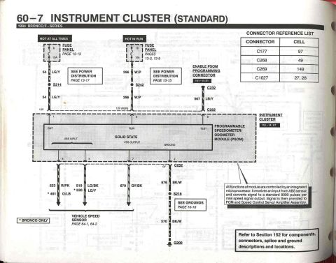
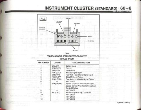
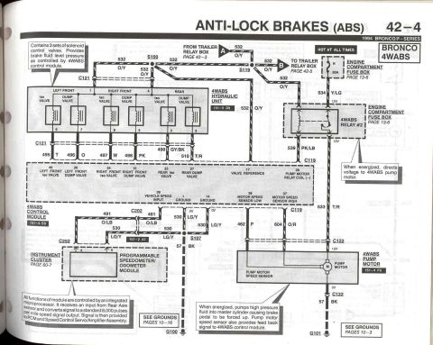
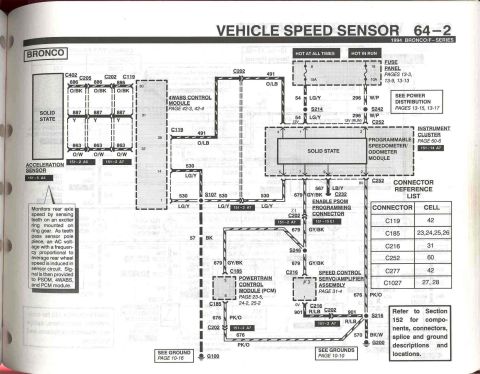
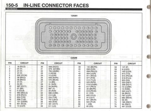



Chassis electrical wiring diagram from a service manual showing color-coded circuits for EEC relay, fuel injectors and ignition.
Part of 1992-1996 Ford Bronco Wiring Diagrams
This is a scanned page from a Haynes-style repair manual, Chapter 12 'Chassis electrical system,' page 12-33, showing an engine control/fuel injection wiring diagram for a Ford EFI engine with six fuel injectors (consistent with the 4.9L inline six). The diagram traces power from three fusible links (N, D, W, plus Z), labeled 'HOT AT ALL TIMES' and 'HOT IN RUN OR START', through the EEC power relay and fuel pump relay to the fuel injectors, throttle air bypass valve solenoid, canister purge solenoid, EGR vacuum regulator solenoid, thermactor air bypass solenoid, inertia fuel shut-off switch, and rear tank select circuit. It also shows the ignition coil, EEC distributor TFI module, noise capacitor, spark plugs, and VIP test connector. Wire colors are labeled throughout (YEL, WHT/LT BLU, RED, BLK, TAN/ORG, TAN/RED, TAN/LT GRN, GRY/WHT, BRN, DK GRN/YEL, RED/LT BLU, BLK/ORG, RED/YEL, DK GRN). Callouts at lower left split circuits between 1987 and 1988 model years, indicating this specific diagram applies to those years. A reader can trace power distribution and wire colors for the EEC/fuel system circuits shown.
This document covers 1987-1988, which may differ from this 1994 Ford Bronco.
Is this accurate? Sign in to help verify it.
Frequently asked questions
- What color are the fuel injector wires in this diagram?
- Each injector is fed by a RED wire; the control-side wires alternate: injectors 1, 3 and 5 use TAN/ORG, and injectors 2, 4 and 6 use TAN/RED.
- Which fuse links power the EEC and fuel pump circuits?
- Fuse Link N (hot at all times, YEL wire) and Fuse Link D (hot in run or start, WHT/LT BLU wire) feed the EEC power relay, Fuse Link Z (BLK/RED) is also shown, and Fuse Link W (hot at all times, YEL wire) feeds the fuel pump relay.
- What wire colors connect to the fuel pump relay?
- The fuel pump relay is fed by YEL from Fuse Link W (hot at all times), with RED and TAN/LT GRN wires on the output/control side.
- What wire colors go to the inertia fuel shut-off switch?
- The inertia fuel shut-off is shown with a DK GRN/YEL wire in and a RED/YEL wire out toward the rear tank select circuit.
- What components are on the EEC power relay output circuit?
- The RED output feed runs to the fuel injectors, throttle air bypass valve solenoid (with diode), canister purge solenoid, EGR vacuum regulator solenoid, and the TFI module/ignition circuits.

No comments yet.