Home/
Registry/
Ford/
Bronco/
1992-1996/
“Buckin Bronco”/
Photo
supermotors.net/registry/media/1137630
1996 Ford Bronco 5.0L Engine Controls Wiring Diagram - EGR, IAC, Purge, PCM
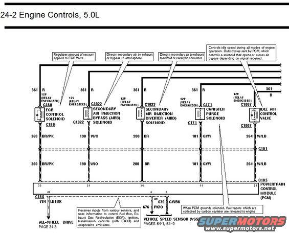
Engine controls wiring diagram for 5.0L showing EGR control, air injection bypass/diverter, canister purge and idle air control valve circuits.
This document is page 24-2 of a Ford wiring diagram set covering Engine Controls for the 5.0L engine. It shows the power and control circuits for five emission/engine-control solenoids and valves: the EGR Control Solenoid (connector C180, wire 360 BR/PK to PCM pin 33), the Secondary Air Injection Bypass (AIRB) Solenoid (C1022, wire 190 W/O), the Secondary Air Injection Diverter (AIRD) Solenoid (C1023, wire 200 BR to PCM pin 34), the Canister Purge Solenoid (C171, wire 101 GY/Y to PCM pin 11), and the Idle Air Control Valve (C1007, wire 264 W/LB to PCM pin 21). All devices receive 12V on circuit 361 R when the relay is energized. Ground/control-side wires pass through connector C101 to the Powertrain Control Module (PCM) at connector C185. Additional PCM circuits shown include wire 784 LB/BK (pin 42) to the All-Wheel Drive circuit (page 34-3) and wires 676 PK/O and 679 GY/BK (pins 6 and 3) to the Vehicle Speed Sensor (pages 64-1, 64-2). Descriptive callouts explain each component's function, such as the IAC valve's duty-cycled idle control and the canister purge solenoid releasing carbon-canister fuel vapors when grounded by the PCM.
Is this accurate? Sign in to help verify it.
Frequently asked questions
- What wire color and circuit number goes to the EGR Control Solenoid on the 5.0L?
- The EGR Control Solenoid uses wire 360 BR/PK (brown/pink) through connector C180, running through C101 to PCM pin 33. It gets 12V on circuit 361 R when the relay is energized.
- Which PCM pin controls the Canister Purge Solenoid?
- The Canister Purge Solenoid connects through connector C171 on wire 101 GY/Y to PCM pin 11. When the PCM grounds the solenoid, fuel vapors collected by the carbon canister are released to the engine.
- What is the wire for the Idle Air Control Valve?
- The Idle Air Control Valve (connector C1007) uses wire 264 W/LB to PCM pin 21, with 12V supplied on circuit 361 R when the relay is energized.
- What do the AIRB and AIRD solenoids do according to this diagram?
- The Secondary Air Injection Bypass (AIRB) Solenoid directs secondary air to the exhaust or bypasses it to atmosphere (wire 190 W/O via C1022). The Secondary Air Injection Diverter (AIRD) Solenoid directs secondary air to the exhaust manifold or catalytic converter (wire 200 BR via C1023 to PCM pin 34).
- Where do the Vehicle Speed Sensor wires from the PCM go?
- PCM pins 6 and 3 connect via wires 676 PK/O and 679 GY/BK to the Vehicle Speed Sensor (VSS), covered on pages 64-1 and 64-2 of the diagram set.
Comments
More from this build














No comments yet.