Home/
Registry/
Ford/
Bronco/
1992-1996/
“Buckin Bronco”/
Photo
supermotors.net/registry/media/1137636
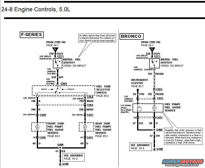
Ford Bronco & F-Series 5.0L Fuel Pump Wiring Diagram - Inertia Switch, Sender
Reference · 1992-1996 BroncoAll 411 wiring diagrams
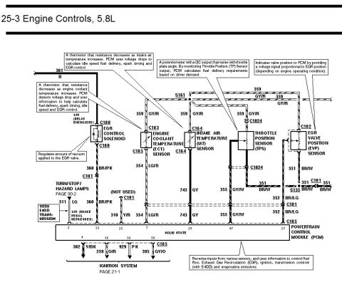
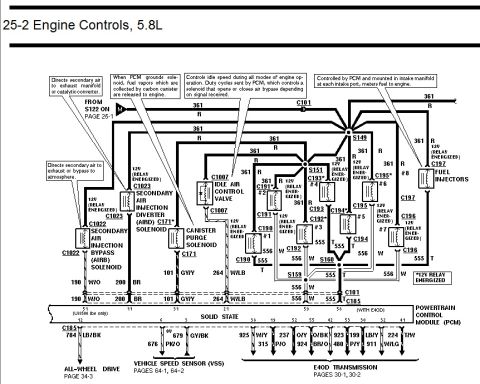
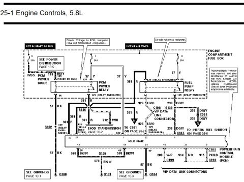
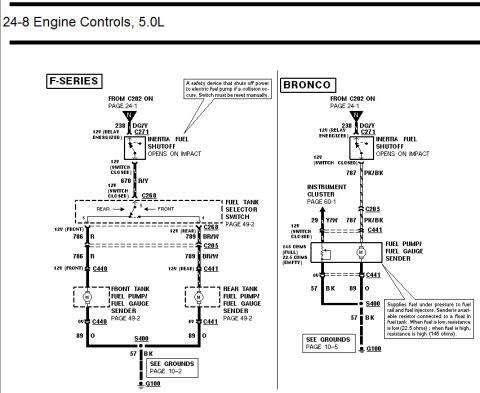
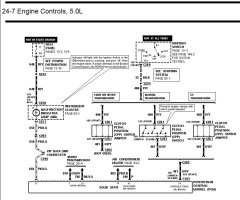
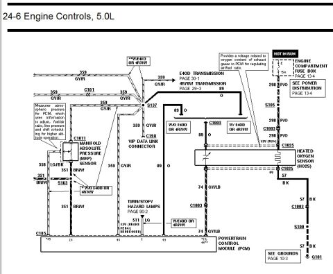
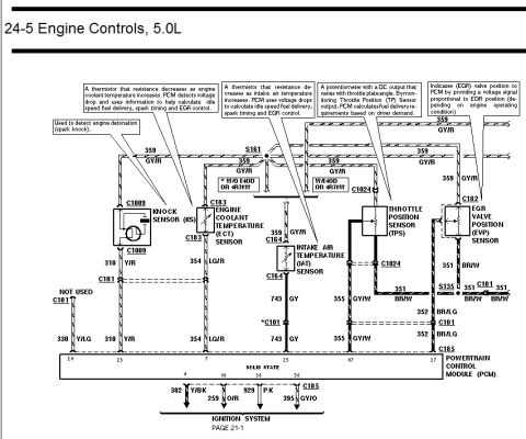
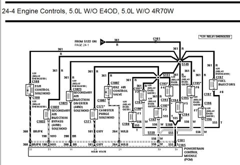
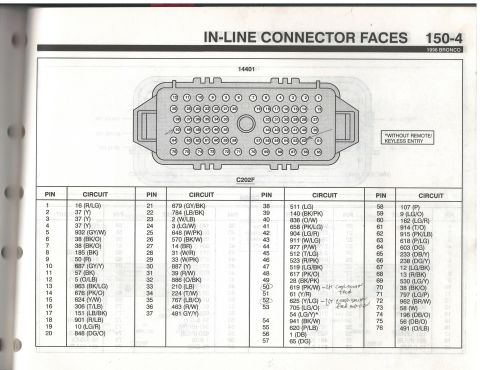
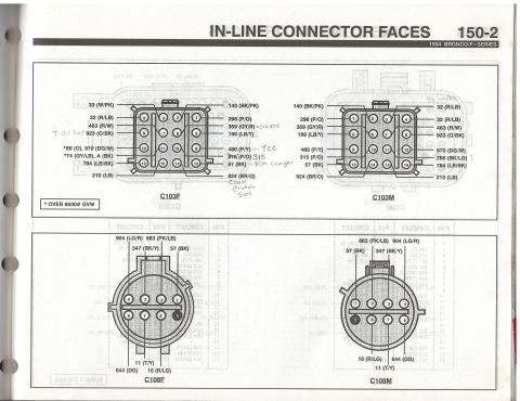
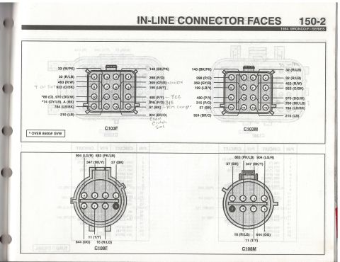
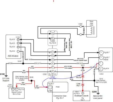








Engine controls wiring diagram for 5.0L showing inertia fuel shutoff, fuel tank pumps and fuel gauge sender circuits for F-Series and Bronco.
Part of 1992-1996 Ford Bronco Wiring Diagrams
This is page 24-8 of a Ford wiring diagram manual covering Engine Controls for the 5.0L engine, showing the fuel pump and inertia fuel shutoff circuits for both F-Series trucks and the Bronco. Power comes from connector C202 (page 24-1) on circuit 238 (DG/Y) through connector C271 to the Inertia Fuel Shutoff switch, described as a safety device that shuts off power to the electric fuel pump in a collision and must be reset manually. On the F-Series side, circuit 670 (R/Y) feeds the Fuel Tank Selector Switch (via C268), which routes 12V to either the front tank pump on circuit 786 (R, via C440) or the rear tank pump on circuit 789 (BR/W, via C441). The Bronco side uses circuit 787 (PK/BK) through C205 and C441 to a single Fuel Pump/Fuel Gauge Sender, with circuit 29 (Y/W) going to the instrument cluster (page 60-1). The sender is a variable resistor: 22.5 ohms empty, 145 ohms full. Grounds run through circuits 89 (O) and 57 (BK) to splice S400 and ground G100 (grounds pages 10-2 and 10-5). Connector references include C202, C205, C268, C271, C440, and C441.
Is this accurate? Sign in to help verify it.
Frequently asked questions
- What does the inertia fuel shutoff switch do on a 5.0L Ford?
- It is a safety device that shuts off power to the electric fuel pump if a collision occurs, and the switch must be reset manually. It opens on impact.
- What wire color and circuit feeds the Bronco fuel pump?
- Circuit 787, a PK/BK (pink/black) wire, feeds the Bronco fuel pump/fuel gauge sender through connectors C205 and C441 when the inertia switch is closed (12V).
- What are the fuel gauge sender resistance values?
- The sender is a variable resistor connected to a float in the fuel tank: 22.5 ohms when empty (low fuel) and 145 ohms when full (high fuel).
- How does the F-Series dual-tank fuel pump wiring differ from the Bronco?
- The F-Series uses a Fuel Tank Selector Switch (via C268) that routes 12V on circuit 786 R to the front tank pump (C440) or circuit 789 BR/W to the rear tank pump (C441). The Bronco has a single fuel pump/sender fed by circuit 787 PK/BK.
- Where does the fuel pump circuit ground?
- Both pumps ground through circuit 89 (orange) to splice S400, then circuit 57 (black) to ground G100, see Grounds page 10-2 (F-Series) or page 10-5 (Bronco).






No comments yet.