Home/
Registry/
Ford/
Bronco/
1992-1996/
“Buckin Bronco”/
Photo
supermotors.net/registry/media/1137634
Ford Bronco 5.0L Engine Controls Wiring Diagram - PCM, MAP & O2 Sensor (24-6)
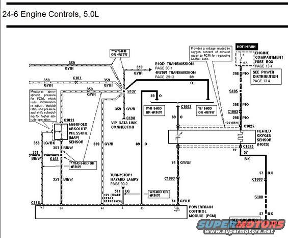
Engine controls wiring diagram for 5.0L showing manifold absolute pressure sensor and heated oxygen sensor circuits to the PCM.
This is page 24-6 of a factory-style wiring diagram covering the Engine Controls system for a 5.0L Ford engine. The diagram traces circuits between the Powertrain Control Module (PCM, connector C185) and several components: the Manifold Absolute Pressure (MAP) sensor at connector C1011, the Heated Oxygen Sensor (HO2S) at connector C1025, and the VIP Data Link Connector (C198). Wire circuits shown include 359 GY/R (gray/red reference), 358 LG/BK, 351 BR/W, 298 P/O (power in RUN through fuse E, 15A, in the Engine Compartment Fuse Box, page 13-4), 89 O, 74 GY/LB, 511 LG (12V brake pedal depressed signal from turn/stop/hazard lamps, page 90-2), and 57 BK ground routed through S100 to G101 (see Grounds, page 10-3). Splices S137, S163, S105 and S100 and connectors C101 and C1003 are identified. Notes distinguish wiring differences with or without the E4OD or 4R70W transmissions, with cross-references to E4OD Transmission page 30-1 and 4R70W Transmission page 29-3. Explanatory callouts describe the MAP sensor's role in adjusting fuel/air ratio, line pressure, and shift scheduling at altitude, and the HO2S's role in providing an exhaust oxygen voltage signal to the PCM.
Is this accurate? Sign in to help verify it.
Frequently asked questions
- Which fuse powers the heated oxygen sensor (HO2S) on the 5.0L?
- Fuse E, a 15A fuse in the Engine Compartment Fuse Box (see page 13-4), supplies power hot in RUN through circuit 298 P/O to the HO2S at connector C1025.
- What wire colors connect to the MAP sensor?
- The MAP sensor (connector C1011) uses circuit 359 GY/R (reference), 358 LG/BK, and 351 BR/W wires to the PCM.
- What does the MAP sensor do according to this diagram?
- It measures atmospheric pressure for the PCM, which uses the information to adjust fuel/air ratio, line pressure, and shift scheduling for higher altitude operation.
- Where does the oxygen sensor ground circuit go?
- Circuit 57 BK runs from the HO2S through C1003 and splice S100 to ground G101 (see Grounds, page 10-3).
- What signal comes from the brake circuit to the PCM?
- Circuit 511 LG carries 12V when the brake pedal is depressed, coming from the Turn/Stop/Hazard Lamps circuit (page 90-2), used with the E4OD or 4R70W transmission.
Comments
More from this build














No comments yet.