Home/
Registry/
Ford/
Bronco/
1992-1996/
“Buckin Bronco”/
Photo
supermotors.net/registry/media/1137640
Ford Bronco 5.8L Engine Controls Wiring Diagram: MAP & O2 Sensor (Page 25-4)
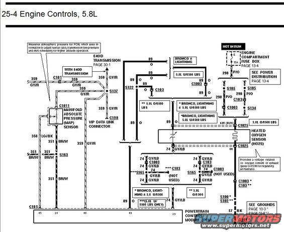
Engine controls wiring diagram for 5.8L showing manifold absolute pressure sensor and heated oxygen sensor circuits to the PCM.
This is page 25-4 of a Ford factory-style wiring diagram set covering Engine Controls for the 5.8L engine, applicable to Bronco, Lightning, and F-Series trucks (with under-8500 lb and over-8500 lb GVW variants distinguished by asterisk footnotes). The diagram shows the Manifold Absolute Pressure (MAP) sensor (connector C1011) with a note explaining it measures atmospheric pressure for the PCM to adjust fuel/air ratio, transmission line pressure, and shift scheduling at altitude. It also shows the Heated Oxygen Sensor (HO2S), which provides a voltage related to exhaust oxygen content, powered through a 15A fuse (position E) in the engine compartment fuse box on circuit 298 P/O (hot in run). Signal circuits include 359 GY/R (MAP signal, also feeding the VIP Data Link Connector C198 and E4OD transmission on page 30-1), 358 LG/BK, 351 BR/W (return/ground via splice S163 and connector C185), 89 O (reference), and 74 GY/LB (HO2S signal to PCM pin 49). Ground is via 57 BK to G101/G100. PCM pins 45, 26, 46, 49, and 29 are shown. Cross-references point to Power Distribution page 13-4, Grounds pages 10-3/10-5, and E4OD Transmission page 30-1.
Is this accurate? Sign in to help verify it.
Frequently asked questions
- What fuse powers the heated oxygen sensor on the 5.8L Bronco?
- A 15A fuse (position E) in the engine compartment fuse box, hot in run, feeding circuit 298 P/O (see Power Distribution page 13-4).
- What does the MAP sensor do according to this diagram?
- It measures atmospheric pressure for the PCM, which uses the information to adjust fuel/air ratio, transmission line pressure, and shift scheduling for higher altitude operation.
- What wire colors are used for the MAP sensor circuits?
- Circuit 359 GY/R (signal), 358 LG/BK, and 351 BR/W (via splice S163 and connector C185).
- What is the HO2S signal wire circuit?
- Circuit 74 GY/LB, running from the heated oxygen sensor through C1025/C1003/C103 and splice S165 to the PCM.
- Where are the grounds for this circuit shown?
- Circuit 57 BK grounds at G101 (or G100 depending on application); see Grounds page 10-3 or page 10-5.
Comments
More from this build














No comments yet.