Home/
Registry/
Hyundai/
Genesis Coupe/
2010-2016/
“Coupe”/
Photo
supermotors.net/registry/media/1164259
Hyundai Genesis Coupe Power Distribution Wiring Diagram SD110-7: Fuse Feeds
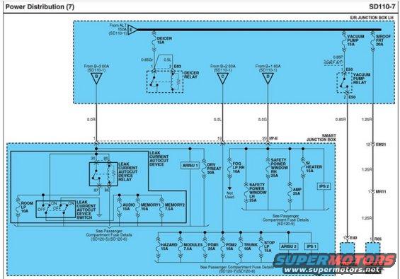
Power distribution wiring diagram showing junction box relays and fuses feeding deicer, vacuum pumps and compartment loads.
Part of 2010-2016 Hyundai Genesis Coupe Wiring Diagrams
This is page SD110-7, "Power Distribution (7)," of a factory wiring diagram showing how battery/alternator power is distributed through the E/R (engine room) Junction Box LH and the Smart Junction Box. Power arrives from the alternator via a 150A fuse (from SD110-1) and feeds the DEICER 15A fuse (through the E63 Deicer Relay), the VACUUM PUMP 15A fuse (through the E50 Vacuum Pump Relay, noted for G4KF A/T applications, feeding the vacuum pump via connector E40), and the S/ROOF FRT 20A fuse, which feeds the Sunroof Control Module through connectors EM21, MR11, and R05 using 1.25R wiring. Three 60A feeds (B+1, B+2, B+3) run through 5.0-gauge wires (5.0R, 5.0L, 5.0G) into the Smart Junction Box, supplying fuses including ROOM LP 10A, AUDIO 15A, MEMORY1 10A, MEMORY2 7.5A (via the Leak Current Autocut Device relay/switch), ARISU 1, DRV P/SEAT 30A, FOG LP RR 10A (not used), SAFETY POWER WINDOW LH/RH 25A, AMP 25A, S/HEATER 15A, IPS 1/2, HAZARD 15A, MODULES 7.5A, PDM1 25A, PDM2 10A, TRUNK 10A, and STOP LP 15A. Cross-references point to passenger compartment fuse details on pages SD120-5 through SD120-9.
Is this accurate? Sign in to help verify it.
Frequently asked questions
- What fuses does the Smart Junction Box receive power for on this diagram?
- Fuses shown fed through the Smart Junction Box include ROOM LP 10A, AUDIO 15A, MEMORY1 10A, MEMORY2 7.5A, DRV P/SEAT 30A, FOG LP RR 10A (marked Not Used), SAFETY POWER WINDOW LH and RH 25A, AMP 25A, S/HEATER 15A, HAZARD 15A, MODULES 7.5A, PDM1 25A, PDM2 10A, TRUNK 10A, STOP LP 15A, plus ARISU 1, ARISU 2, IPS 1, and IPS 2.
- What powers the sunroof control module?
- The S/ROOF FRT 20A fuse in the E/R Junction Box LH feeds the Sunroof Control Module via 1.25R wiring through connectors EM21 (pin 12), MR11 (pin 1), and R05 (pin 1).
- How is the vacuum pump powered?
- Through the VACUUM PUMP 15A fuse and the Vacuum Pump Relay (connector E50, noted for G4KF A/T), then via a 0.85R wire to pin 1 of connector E40 at the vacuum pump.
- What are the main feed wires into the Smart Junction Box?
- Three 60A feeds from SD110-1: B+3 via 5.0R to pin 1, B+2 via 5.0L to pin 19, and B+1 via 5.0G to pin 20 (I/P-E).
- What controls the audio and memory fuses in this diagram?
- The AUDIO 15A, MEMORY1 10A, MEMORY2 7.5A, and ROOM LP 10A fuses are switched through the Leak Current Autocut Device relay and switch inside the Smart Junction Box.
Comments
More from this build









No comments yet.