Home/
Registry/
Hyundai/
Genesis Coupe/
2010-2016/
“Coupe”/
Photo
supermotors.net/registry/media/1164323
Hyundai Genesis Coupe 3.8L MFI Control Wiring Diagram SD313-9 (G6DA Lambda)
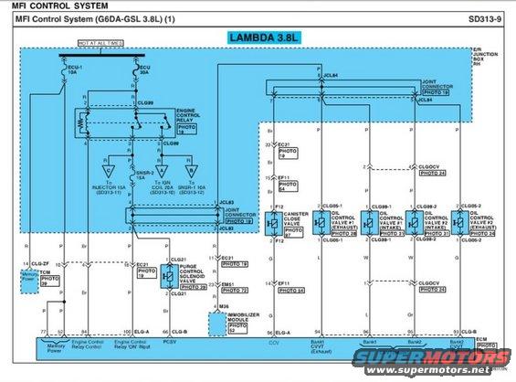
Wiring diagram of a 3.8L MFI control system showing the ECU, relays, valves and color-coded circuits.
Part of 2010-2016 Hyundai Genesis Coupe Wiring Diagrams
This document is page SD313-9 of a Hyundai wiring diagram set covering the MFI (Multiport Fuel Injection) Control System for the G6DA-GSL 3.8L Lambda engine. It shows the power distribution from the E/R (engine room) junction box RH, with the ECU-1 10A and ECU 30A fuses feeding the engine control relay (connector CLG99), which in turn feeds the Injector 15A, Ignition Coil 20A, SNSR-1 10A, and SNSR-2 15A fuses (cross-referenced to sheets SD313-10, -11, -12). The diagram traces circuits through joint connectors JCL83 and JCL84 to the canister close valve (F12), purge control solenoid valve (CLG21), immobilizer module (M36), TCM memory power (CLG-ZF), and four CVVT oil control valves, Bank 1 and Bank 2, intake (CLG98-1/CLG98-2) and exhaust (CLG05-1/CLG05-2). ECM pin assignments are given along the bottom: pins 77/52 memory power, 94 engine control relay control, 100 relay 'ON' input, 66 PCSV, 86 CCV, and pins 94/96/95/93 for the CVVT valves. Wire colors (R, P, B, Br, G, L, W, Gr) and photo reference numbers for connector locations are included throughout.
Is this accurate? Sign in to help verify it.
Frequently asked questions
- What fuses power the MFI control system on the 3.8L Lambda engine?
- The ECU-1 10A and ECU 30A fuses (hot at all times, in the E/R junction box RH) feed the engine control relay, which supplies the Injector 15A, IGN Coil 20A, SNSR-1 10A, and SNSR-2 15A fuses.
- Which ECM pins control the CVVT oil control valves?
- Per the diagram: pin 94 for Bank 1 CVVT exhaust, pin 96 for Bank 1 intake, pin 95 for Bank 2 intake, and pin 93 (CLG-B) for Bank 2 CVVT exhaust.
- What connectors are used for the oil control valves?
- CLG05-1 (Bank 1 exhaust OCV), CLG98-1 (Bank 1 intake OCV), CLG98-2 (Bank 2 intake OCV), and CLG05-2 (Bank 2 exhaust OCV).
- Where does the purge control solenoid valve connect to the ECM?
- The purge control solenoid valve (connector CLG21, Photo 29) connects to ECM pin 66 (CLG-B), labeled PCSV.
- What sheet references cover the injector, coil, and sensor fuses?
- Injector 15A is on SD313-11, IGN Coil 20A on SD313-10, and SNSR-1 10A on SD313-12.
Comments
More from this build









No comments yet.