Home/
Registry/
Hyundai/
Genesis Coupe/
2010-2016/
“Coupe”/
Photo
supermotors.net/registry/media/1164427
Hyundai Genesis Coupe Turn & Hazard Lamps Wiring Diagram SD925-2

Reference · 2010-2016 Genesis CoupeAll 79 wiring diagrams
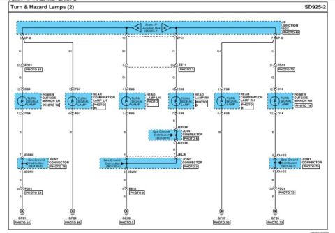
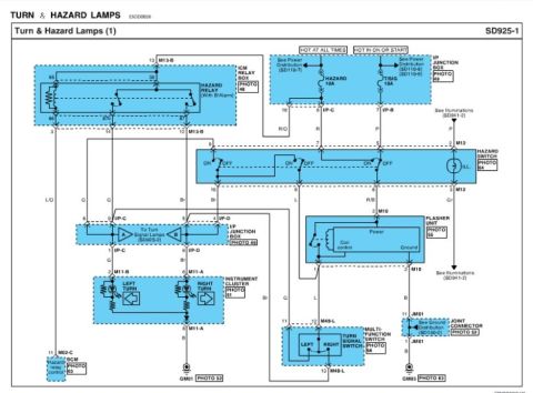
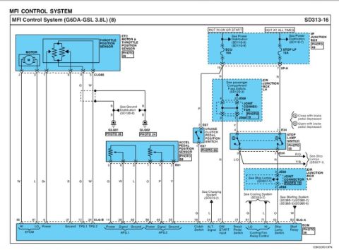
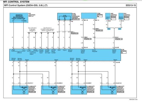
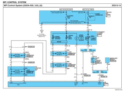








Wiring diagram showing turn signal lamp circuits for front, rear and mirror-mounted combination lamps.
Part of 2010-2016 Hyundai Genesis Coupe Wiring Diagrams
This is page SD925-2 of a factory-style wiring diagram titled "Turn & Hazard Lamps (2)". It shows the downstream circuits of the turn signal and hazard lamp system, fed from the I/P (instrument panel) Junction Box via connectors A and B (continued from sheet SD925-1). Six turn signal lamp circuits are diagrammed: the power outside mirror turn signal lamps LH (connector D04) and RH (connector D14), the rear combination turn lamps LH (F57) and RH (F58), and the head lamp turn signals LH (E95) and RH (E96). Wire colors are labeled (G = green, Br = brown, Gr = gray, B = black for grounds). Intermediate connectors FD11, FD21, and EE11 are shown with pin numbers, and grounds are distributed through joint connectors JDDRI, JELIN, JEFEM, and JDASS (referencing Ground Distribution sheets SD130-4, SD130-6, and SD130-7). Final ground points are GF01, GF04, GE03, GF07, and GF05. Photo callouts (e.g., PHOTO 49, 54, 72, 76, 79, 86, 2, 20, 96) reference connector location photos elsewhere in the manual. A reader can trace each turn signal lamp circuit from junction box output pin through connectors to its ground point.
Is this accurate? Sign in to help verify it.
Frequently asked questions
- Which connector serves the LH power outside mirror turn signal lamp?
- Connector D04, with power at pin 12 (green wire) and ground at pin 13 (black wire) through joint connector JDDRI to ground GF01.
- Where does the turn/hazard lamp power on this diagram come from?
- From the I/P Junction Box, continued from sheet SD925-1 via connectors A and B (see PHOTO 49).
- What connectors are used for the rear combination turn signal lamps?
- F57 for the left rear combination lamp (pin 1 power, pin 6 ground to GF04) and F58 for the right rear combination lamp (pin 1 power, pin 6 ground to GF07).
- What wire colors are used in the turn signal circuits shown?
- Green (G) and gray (Gr) feed wires on the right side, green and brown (Br) on the left/center circuits, with black (B) wires for all grounds.
- Which ground distribution sheets are referenced for the joint connectors?
- SD130-4 for JELIN and JEFEM, SD130-6 for JDDRI, and SD130-7 for JDASS.

No comments yet.