Home/
Registry/
Hyundai/
Genesis Coupe/
2010-2016/
“Coupe”/
Photo
supermotors.net/registry/media/1168702
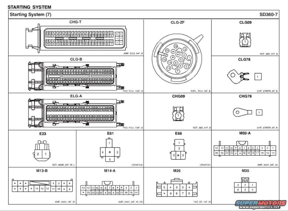
2010 Hyundai Genesis Coupe Starting System Connector Diagram SD360-7
Reference · 2010-2016 Genesis CoupeAll 79 wiring diagrams
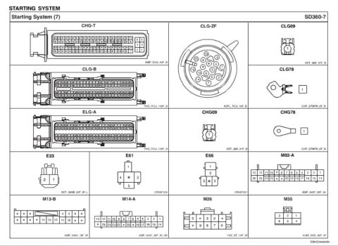
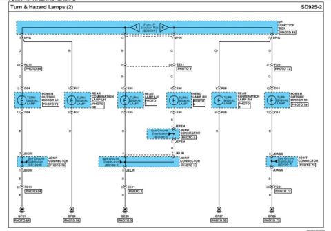
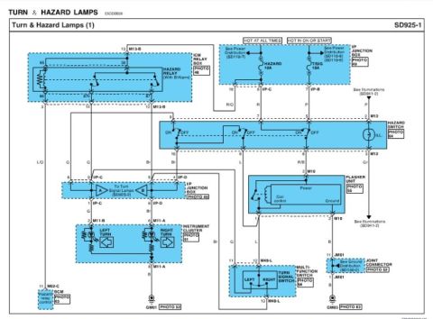
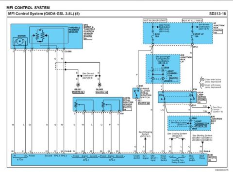
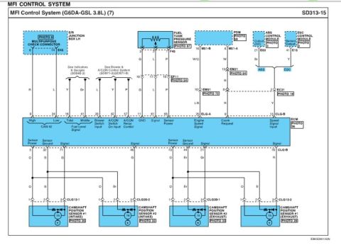








Starting-system connector diagram showing connector pin layouts, terminal positions and part numbers for the wiring harness.
Part of 2010-2016 Hyundai Genesis Coupe Wiring Diagrams
This document is page SD360-7, "Starting System (7)," from a Hyundai wiring diagram / electrical troubleshooting manual, showing connector face views for the starting system circuit. It illustrates sixteen connectors with their pin layouts and housing part codes: CHG-T (94-pin ECU connector, AMP_ECU_94F_B), CLG-B and ELG-A (100-pin PCU connectors, PKD_PCU_100F_B), CLG-ZF (16-pin round TCU connector, KSTL_TCU_16F_B), single-pin connectors CLG09 and CHG09 (KET_58X_01F_B), starter terminals CLG78 and CHG78 (CHT_STMTR_8T_N), plus body/engine harness connectors E23 (2-pin), E61 and E66 (5-pin), M02-A and M14-A (26-pin), M13-B (18-pin), M26 (10-pin), and M35 (6-pin). Each drawing shows the connector as viewed at its mating face with numbered cavities (unused cavities marked with a star). A reader can use this page to identify pin positions when probing or back-probing starting-system circuits, and to identify connector housings by their manufacturer codes (AMP, KET, KUM, YAZ, PKD, KSTL, CHT). The page carries document code EBKSD0080GN. It was uploaded as part of a set covering a 2010 Hyundai Genesis Coupe (BK1) and appears consistent with that vehicle's service literature.
Is this accurate? Sign in to help verify it.
Frequently asked questions
- What connectors are shown on the Starting System (7) SD360-7 page?
- CHG-T, CLG-ZF, CLG09, CLG78, CLG-B, CHG09, CHG78, ELG-A, E23, E61, E66, M02-A, M13-B, M14-A, M26, and M35.
- How many pins does the CHG-T ECU connector have?
- CHG-T is a 94-pin connector with housing code AMP_ECU_94F_B; pin numbers run up to 94 with unused cavities marked by stars.
- What is the pin layout of connector M35?
- M35 is a 6-pin connector (housing KUM_DSD_06F_W) with pins 3, 2, 1 in the top row and 6, 5, 4 in the bottom row.
- What housing part code is used for the CLG-B and ELG-A connectors?
- Both CLG-B and ELG-A are 100-pin connectors with housing code PKD_PCU_100F_B.
- What is the CLG-ZF connector?
- CLG-ZF is a 16-pin round TCU connector with housing code KSTL_TCU_16F_B, with pins 1 through 16 arranged in a circular pattern.

No comments yet.