Home/
Registry/
Ford/
Bronco/
1980-1986/
“That dirty old truck”/
Photo
supermotors.net/registry/media/1168577
Ford Camber/Caster Adjuster Cam Rotation Offset Chart - Alignment Bushing Table

Reference · 1980-1986 BroncoAll 40 service procedures
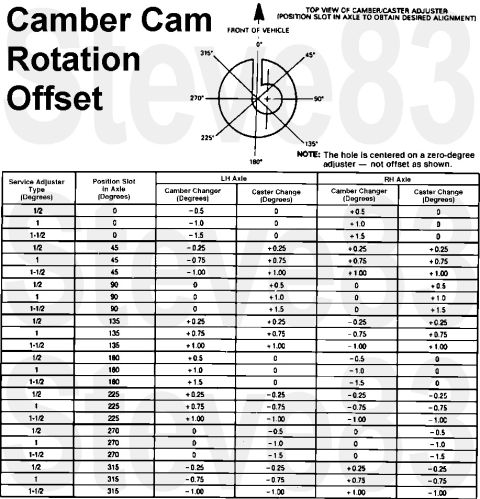


Camber Cam Rotation Offset
IF THE IMAGE IS TOO SMALL, click it.
See also: .
 .
 .
 .
 .

Part of 1980-1986 Ford Bronco Service Procedures
This document is a 'Camber Cam Rotation Offset' reference chart for front-end alignment using camber/caster adjuster cams (bushings). A top-view diagram of the camber/caster adjuster shows how the position slot in the axle corresponds to degree markings from 0° to 315° in 45° increments, oriented relative to the front of the vehicle. A note clarifies that the hole is centered on a zero-degree adjuster and is not offset as shown in the drawing. The main table lists three service adjuster types (1/2, 1, and 1-1/2 degrees) at each of eight slot positions (0°, 45°, 90°, 135°, 180°, 225°, 270°, 315°) and gives the resulting camber change and caster change, in degrees, separately for the left-hand (LH) and right-hand (RH) axles. For example, a 1-degree adjuster at 0° gives -1.0° camber change on the LH axle and +1.0° on the RH axle, with no caster change; at 90°, camber is unchanged but caster changes +1.0° on both sides. This allows a technician to select the proper adjuster size and rotation angle to achieve desired camber and caster corrections during a front alignment.
Is this accurate? Sign in to help verify it.
Frequently asked questions
- What camber change does a 1-degree adjuster at the 0° slot position produce?
- Per the chart, a 1-degree adjuster at 0° gives -1.0° camber change on the LH axle and +1.0° on the RH axle, with 0 caster change on both sides.
- Which adjuster position changes caster without changing camber?
- The 90° and 270° slot positions produce 0 camber change; 90° adds positive caster (+0.5, +1.0, or +1.5 depending on adjuster size) and 270° adds negative caster on both axles.
- What adjuster sizes are covered in the table?
- Three service adjuster types: 1/2 degree, 1 degree, and 1-1/2 degrees.
- Is the hole in a zero-degree adjuster offset?
- No. The note states the hole is centered on a zero-degree adjuster, it is not offset as shown in the diagram.
- How is the adjuster oriented in the diagram?
- The diagram is a top view of the camber/caster adjuster with 0° toward the front of the vehicle, and slot positions marked every 45° from 0° to 315°.
No comments yet.