Ford 351M / 400 V8 Valve Clearance & Hydraulic Tappet Adjustment Procedure
Reference · 1980-1986 BroncoAll 40 service procedures
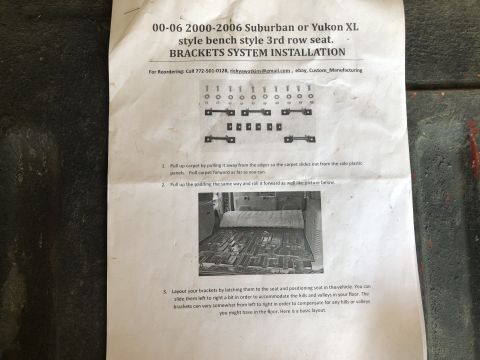
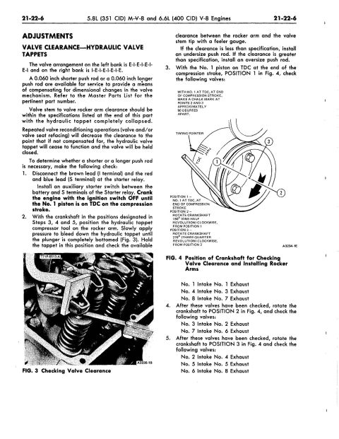







Service-manual page for Ford 5.8L (351 CID) and 6.6L (400 CID) V8 valve clearance (hydraulic tappet) adjustment: cranking-to-TDC checking procedure and 0.060 in longer/shorter service push rods.
Part of 1980-1986 Ford Bronco Service Procedures
This is page 21-22-6 of a Ford factory service manual section covering the 5.8L (351 CID) M-V-8 and 6.6L (400 CID) V-8 engines. It presents the ADJUSTMENTS section on valve clearance with hydraulic valve tappets. The page explains that the left bank valve arrangement is E-I-E-I-E-I-E-I and the right bank is I-E-I-E-I-E-I-E, and that 0.060-inch shorter or longer push rods are available to compensate for dimensional changes from valve reconditioning. It gives a five-step procedure for checking valve clearance: disconnecting starter relay leads, cranking the engine with an auxiliary starter switch until No. 1 piston reaches TDC on the compression stroke, bleeding down each hydraulic tappet with a compressor tool (T71P-6513-A shown in Fig. 3), and measuring clearance between the rocker arm and valve stem tip with a feeler gauge. Fig. 4 illustrates the three crankshaft positions (TDC, plus 180° and 270° rotations) marked with chalk 90 degrees apart, and the page lists exactly which intake and exhaust valves to check at each of the three positions. Readers learn how to determine whether an undersize or oversize push rod is needed for this engine family.
Is this accurate? Sign in to help verify it.
Frequently asked questions
- What is the valve arrangement on the Ford 351M/400 V8?
- The valve arrangement on the left bank is E-I-E-I-E-I-E-I and on the right bank is I-E-I-E-I-E-I-E.
- What push rod sizes are available to correct valve clearance on the 351M/400?
- A 0.060 inch shorter push rod or a 0.060 inch longer push rod are available for service; refer to the Master Parts List for the pertinent part number. Install an undersize push rod if clearance is less than specification, or an oversize push rod if it is greater.
- Which valves are checked with the No. 1 piston at TDC on the compression stroke (Position 1)?
- No. 1 Intake, No. 1 Exhaust; No. 4 Intake, No. 3 Exhaust; No. 8 Intake, No. 7 Exhaust.
- How are crankshaft Positions 2 and 3 reached for the valve clearance check?
- Position 2 is reached by rotating the crankshaft 180° (one-half revolution) clockwise from Position 1; Position 3 by rotating 270° (three-quarter revolution) clockwise from Position 2. Chalk marks at points 2 and 3 should be approximately 90 degrees apart.
- How is the hydraulic tappet clearance measured?
- Position the hydraulic tappet compressor tool on the rocker arm, slowly apply pressure to bleed down the tappet until the plunger is completely bottomed, hold it there, and check clearance between the rocker arm and valve stem tip with a feeler gauge.






No comments yet.