Home/
Registry/
Ford/
Bronco/
1980-1986/
“That dirty old truck”/
Photo
supermotors.net/registry/media/1168578
1995 Ford Bronco/F-Series Instrument Cluster Pinout - C250 & C251 Connectors

Reference · 1980-1986 BroncoAll 92 wiring diagrams
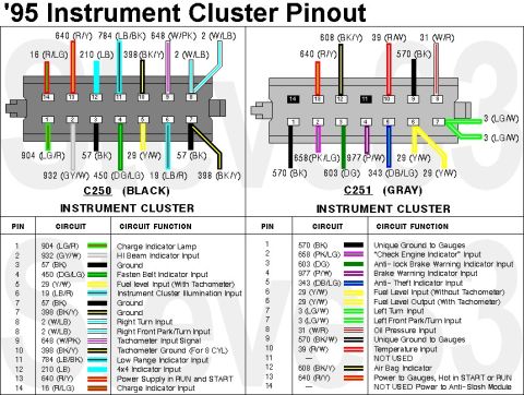
'95 Gasoline Instrument Cluster Connector Pinouts
IF THE IMAGE IS TOO SMALL, click it.
See also:
Part of 1980-1986 Ford Bronco Wiring Diagrams
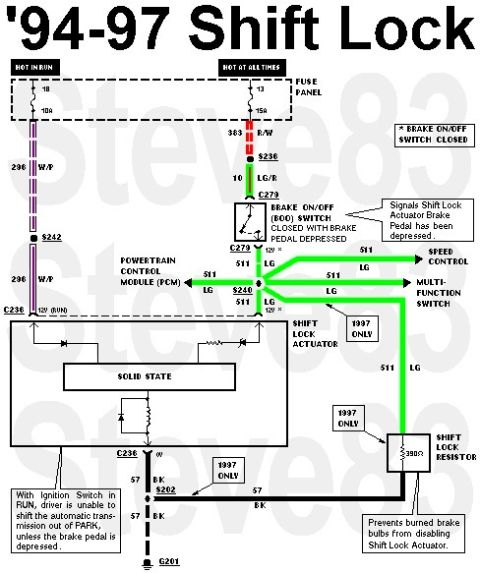
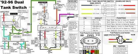
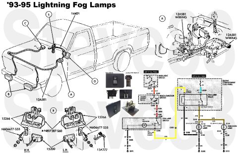
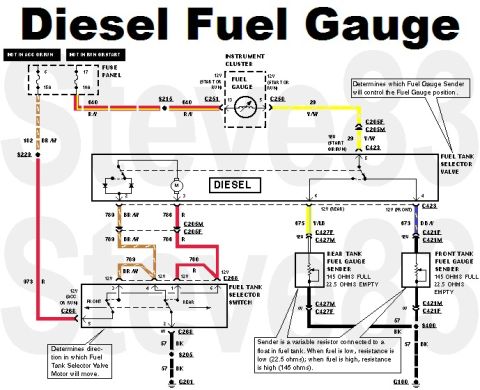
This document is a pinout reference for the 1995 ("'95") instrument cluster connectors, showing the two connectors on the back of the gauge cluster: C250 (black) and C251 (gray). Each connector is illustrated with its 14 pin positions and the wire circuit numbers and color codes attached to each pin. Below each connector illustration is a table listing pin number, circuit number with wire color abbreviation, and circuit function. C250 covers functions such as the charge indicator, high beam indicator, grounds, fasten belt indicator, fuel level input (with tachometer), cluster illumination, right turn/right front park-turn, tachometer signal and ground, low range and 4x4 indicators, and power supply in RUN and START. C251 covers gauge grounds, check engine indicator, anti-lock brake warning, brake warning, anti-theft indicator, fuel level input/output, left turn/left front park-turn, oil pressure, temperature, air bag indicator, power to gauges (hot in START or RUN), and the anti-slosh module feed; pins 11 and 14 are noted as not used or partially unused. A reader can use this to trace cluster wiring by circuit number and wire color for diagnosis of gauges and warning lamps. The image carries a "Steve83" watermark.
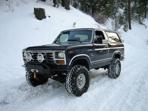
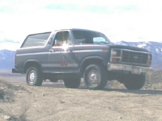
This document covers 1995, which may differ from this 1983 Ford Bronco.
Is this accurate? Sign in to help verify it.
Frequently asked questions
- What are the two instrument cluster connectors shown for the '95 cluster?
- C250, a black connector, and C251, a gray connector, each with 14 pin positions.
- Which pin and wire supply power to the cluster in RUN and START?
- On C250, pin 13 is circuit 640 (R/Y), Power Supply in RUN and START. On C251, pin 13 is also 640 (R/Y), Power to Gauges, Hot in START or RUN.
- Which wire carries the fuel level signal?
- Circuit 29 (Y/W). On C250 pin 5 it is the fuel level input with tachometer; on C251 pin 6 it is the fuel level input without tachometer or fuel level output with tachometer.
- Where does the check engine indicator connect?
- On C251 (gray), pin 2, circuit 658 (PK/LG), labeled "Check Engine Indicator" Input.
- Which pins on the gray connector are not used?
- C251 pin 11 is NOT USED, and pin 14 is listed as NOT USED / Power to Anti-Slosh Module.
No comments yet.