SuperMotors SuperMotors SUPERMOTORS Search: try “orange Bronco on 35s”
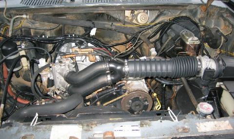
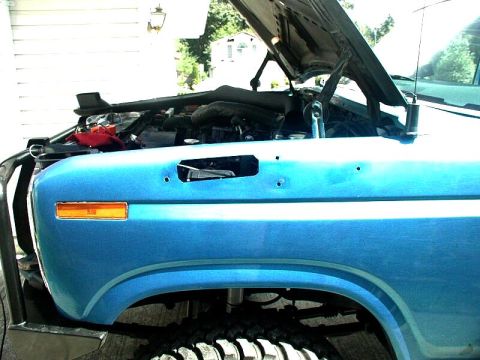
Home/ Registry/ Ford/ Bronco/ 1980-1986/ “That dirty old truck”/ Photo supermotors.net/registry/media/1174826

Ford 4.9L Intake Manifold Installation Diagram - Parts & Torque Specs (TSB 87-08-16)

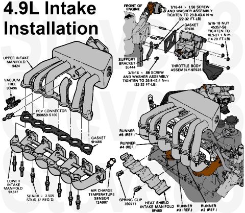
4.9L intake installation exploded view with part numbers and torque specs
4.9L intake installation exploded view with part numbers and torque specsOriginal file
4.9L intake installation exploded view with part numbers and torque specs

Reference · 1980-1986 BroncoAll 61 exploded parts diagrams
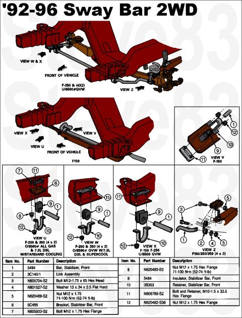
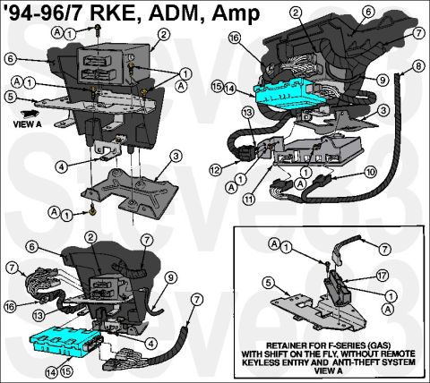
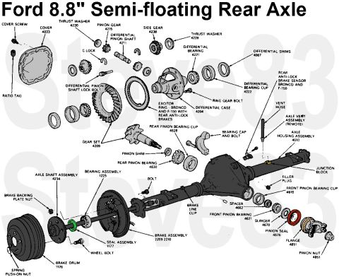
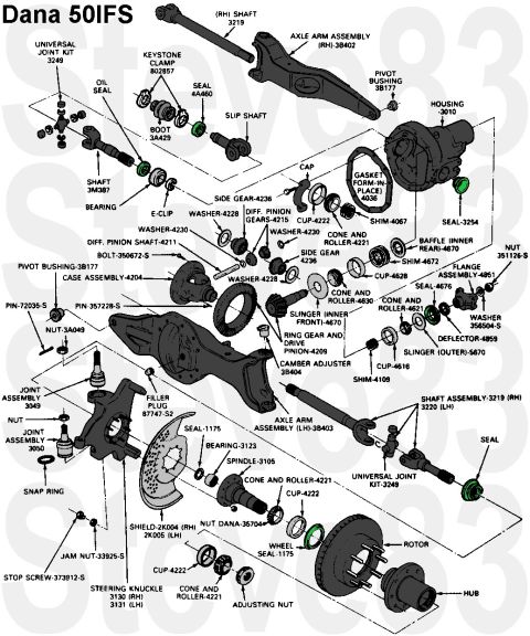
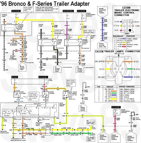
1992-96 Ford F-150/F-250/F-350 2WD Front Sway Bar Diagram & Part Numbers Ford 4.9L Intake Manifold Installation Diagram - Parts & Torque Specs (TSB 87-08-16) 1978-1996 Ford Bronco Tailgate Internals Diagram - Window Regulator & Parts 1994-96 Ford Bronco Tailgate Carpet Panel Diagram - Pushpins & Access Cover Dana 44 IFS TTB Front Axle Exploded Diagram - Ford Bronco & F-150 4x4 Parts 1994-1997 Ford F-Series/Bronco RKE, Anti-Theft & Amp Module Mounting Diagram Ford 8.8" Semi-Floating Rear Axle Exploded Diagram: Parts & Part Numbers Dana 50 IFS Front Axle Exploded Parts Diagram - Ford Part Numbers 61exploded parts diagrams1980-1986 Ford Bronco More reference 1996 Ford Bronco & F-Series Trailer Wiring Diagram - 7-Pin Connector PinoutWiring diagram Ford accessories catalog page with cellular mobile telephone and 40-channel CB emergency radioBrochure Ford door certification label dated 11/95 with GVWR 6300LB, P235/75R15XL tires and VIN 1FMEU15H4TLA76236Spec plate 1992 Ford E4OD Transmission Fault Code Diagnosis Chart - DTC List & SymptomsService procedure Smallblock V8 Coolant Flow Diagram - Ford Engine Cooling Path SchematicSchematic 1996 Ford Bronco/F-Series Starting System - Section 03-06 ContentsManual page Trim panel hole layout photos for positions A, B and C with tape measure readings from the body lineBlueprint Ford 1996 5.8L vehicle information decal with vacuum hose routing diagram and ASF-32P plugVacuum routing SAE and metric bolt torque specification chart by grade in lb-ft and N-mTorque spec '95 F150 fuse and relay chart with fuse panel layout, ATC and Maxi fuse amp tablesFuse chart

TSB 87-08-16: INTAKE MANIFOLD UPPER - 4.9L - REVISED SHOP MANUAL INSTALLATION PROCEDURE

FORD - LIGHT TRUCK: 1987 E-SERIES, F-SERIES, BRONCO

ISSUE: The installation procedure for the upper intake manifold in the 1987 Light Truck Shop Manual, Volume B, Section 24-10-11 is incorrect. Tightening the upper intake manifold support bracket before the seven (7) manifold studs may cause the upper intake manifold to move. This may prevent the upper and lower manifolds from sealing properly and that causes a vacuum leak.

ACTION: When installing the upper intake manifold to the lower intake manifold, the seven (7) manifold studs MUST be tightened to 12-18 ft-lb (16.2-24.4 N-m) before tightening the manifold support bracket. The corrected procedure on page 29 of this TSB should be used in place of the 1987 Light Truck Shop Manual, Volume B, Section 24-10-11.

OTHER APPLICABLE ARTICLES: None
WARRANTY STATUS: "INFORMATION ONLY"

4. Reposition the vacuum harness, then attach the vacuum connection to the fuel pressure regulator.
5. Install a new upper intake gasket on the lower manifold, using the lower manifold dowels to position the gasket.
6. Position the upper intake manifold onto the lower intake manifold, using the dowels of the lower intake to locate. Install the seven studs that attach the upper intake to the lower intake and tighten the seven studs to 16.2-24.4 N-m (12-18 ft-lb).
7. Position the upper intake manifold support onto the boss of the upper intake, located under the throttle body. Install the retaining screw and tighten to 29.8-43.8 N-m (22-32 ft-lb).
8. Install the injector heat shield between the lower intake manifold and the exhaust manifolds. Secure the shield to the lower intake manifold by installing the two spring clips between the intake runners.

See also:
. . .

Part of 1980-1986 Ford Bronco Exploded Parts Diagrams

Owner caption · Photo 6515 of 6546

This document is an exploded parts and installation diagram for the intake manifold system of the Ford 4.9L inline-six engine, titled "4.9L Intake Installation." The left illustration shows an exploded view of the upper intake manifold (9424), lower intake manifold (9K641), the gasket between them (9H486), the vacuum tree (9D496), PCV connector (390659-S100), air charge temperature sensor (12A967), and the seven required 5/16-18 × 2.505 studs. The upper-right illustration details the throttle body assembly (9E926) installation at the front of the engine, including its gasket (9E936), support bracket (9J444), and fastener torque specifications: 7/16-14 × 1.50 screw-and-washer assemblies and 3/8-16 × .88 screw-and-washer assemblies both torqued to 29.8-43.4 N·m (22-32 ft-lb), and 5/16-18 nuts (45357-S8) torqued to 18.9-27.1 N·m (14-20 ft-lb). The lower-right illustration shows the assembled manifold on the engine with runner references (#2 through #5), the intake manifold heat shield (9F460), and its spring clips (390717). Readers can use this document to identify Ford part base numbers, hardware sizes, and torque values needed to remove or install the intake manifolds and throttle body on a fuel-injected 4.9L engine.

Is this accurate? Sign in to help verify it.

Frequently asked questions

What is the torque spec for the 4.9L throttle body screws?
The 7/16-14 × 1.50 and 3/8-16 × .88 screw and washer assemblies are tightened to 29.8-43.4 N·m (22-32 ft-lb); the 5/16-18 nuts (45357-S8) are tightened to 18.9-27.1 N·m (14-20 ft-lb).
What is the part number for the gasket between the upper and lower intake manifolds on the 4.9L?
The gasket between the upper intake manifold (9424) and lower intake manifold (9K641) is base part number 9H486.
How many studs are required to join the 4.9L upper and lower intake manifolds?
Seven 5/16-18 × 2.505 studs are required (marked '5/16-18 × 2.505 STUD (7 REQ'D)').
What part number is the 4.9L throttle body assembly and its gasket?
The throttle body assembly is 9E926 and its gasket is 9E936, mounted with support bracket 9J444.
How is the intake manifold heat shield attached on the 4.9L?
The intake manifold heat shield (9F460) is retained with spring clips, part number 390717.
Comments

No comments yet.

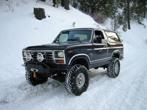
More 1980-1986 Broncos