1986 Ford Bronco Starter Relay Terminal Diagram - S, I, POS & NEG Posts

Reference · 1980-1986 BroncoAll 34 schematics
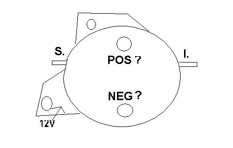


Schematic diagram of a relay/solenoid showing terminal positions including POS, NEG, S, I and 12V.
Part of 1980-1986 Ford Bronco Schematics
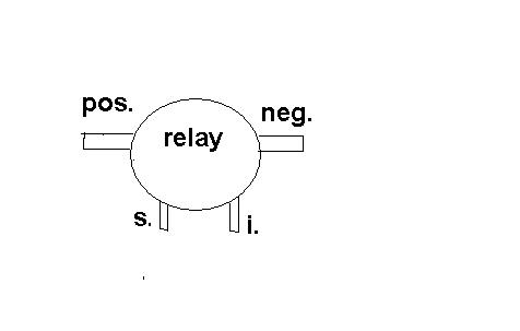
This document is a simple hand-drawn (or computer-sketched) schematic of a starter relay/solenoid, uploaded as "New Relay.JPG" to a 1986 Ford Bronco gallery. The drawing shows an oval relay body with a mounting bracket behind it. Two small terminal posts are drawn on the face of the relay: an upper post labeled "POS?" and a lower post labeled "NEG?", with question marks indicating the uploader is unsure which post is positive and which is negative. Two flat blade/stud terminals extend from the sides of the relay: the left one labeled "S." and the right one labeled "I.", the conventional S (start/switch) and I (ignition) small terminals on this style of relay. A lead at the lower-left mounting ear is labeled "12V". The diagram contains no part numbers, wire colors, amperage values, torque specs, or year/model applicability text. Its purpose appears to be to ask or document which large terminal on the new relay is positive and which is negative, and where the S, I, and 12V connections go. A companion image, "oldRelay.JPG," exists in the same album for comparison.
Is this accurate? Sign in to help verify it.
Frequently asked questions
- What terminals are shown on this starter relay diagram?
- The diagram shows four labeled connection points: a terminal marked "S." on the left side, a terminal marked "I." on the right side, an upper post marked "POS ?", and a lower post marked "NEG ?". A lead at the lower-left is labeled "12V".
- Does the diagram identify which large post is positive and which is negative?
- No. Both large posts are labeled with question marks ("POS ?" and "NEG ?"), indicating the polarity of the two posts is uncertain or being questioned in this drawing.
- Where is the 12V connection shown on this relay diagram?
- The "12V" label points to the lower-left area of the relay near the mounting bracket ear.
- Are the S and I terminals shown on this relay?
- Yes. "S." is drawn as a terminal on the left side of the relay body and "I." is drawn as a terminal on the right side.



No comments yet.