Home/
Registry/
Ford/
Taurus/
1992-1995/
1993 Ford Taurus/
Photo
supermotors.net/registry/media/172397
Ford Taurus 3.2L SHO CCRM Internal Schematic - Constant Control Relay Module

Reference · 1992-1995 TaurusAll 37 wiring diagrams
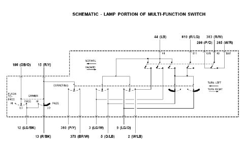
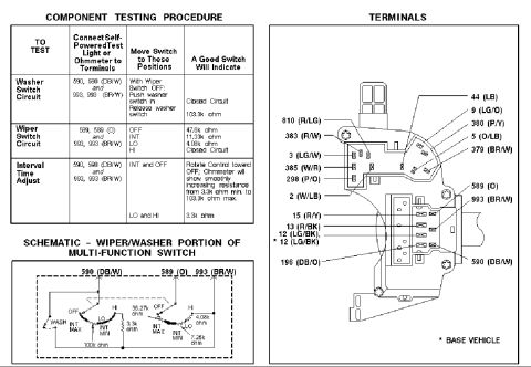
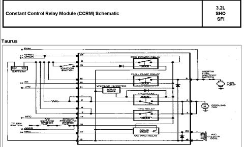
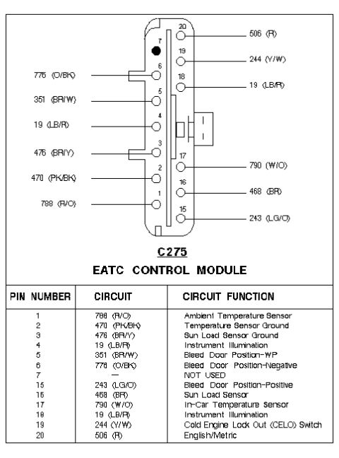
CCRM internal wiring schematic for the 3.2L SHO showing EEC power, fuel pump, LFC, HFC and A/C WAC relays, voltage inverter, inertia switch, fuel pump, cooling fan and A/C clutch coil.
Part of 1992-1995 Ford Taurus Wiring Diagrams
This document is a schematic of the Constant Control Relay Module (CCRM) for the Ford Taurus with the 3.2L SHO SFI engine. It shows the internal layout of the CCRM, including the EEC Power Relay, Fuel Pump Relay, a solid-state Voltage Inverter, the LFC (low fan control) Relay, the HFC (high fan control) Relay, and a solid-state A/C WAC Relay. Module pin numbers are labeled on both sides of the CCRM box (inputs: 24, 8, 13, 12, 18, 14, 1, 2, 6, 7, 17, 21, 22, 16; outputs: 5, 3, 4, 23, 15). Input signals shown include FPM, VPWR (pins 37 and 57), FP (pin 22), LFC (pin 13), HFC (pin 31), ACCS (pin 10), and WAC (pin 54), along with connections to the battery, ignition switch, A/C demand switch, and cyclic pressure switch. Outputs route through the inertia fuel shutoff switch to the fuel pump, to the cooling fan motor, and to the A/C clutch coil. A reader can use this to trace CCRM circuits, identify which internal relay controls each function, and diagnose fuel pump, cooling fan, or A/C clutch faults.
Is this accurate? Sign in to help verify it.
Frequently asked questions
- What relays are inside the Taurus 3.2L SHO CCRM?
- The CCRM contains the EEC Power Relay, Fuel Pump Relay, LFC Relay, HFC Relay, a solid-state Voltage Inverter, and a solid-state A/C WAC Relay.
- Which CCRM pin feeds the fuel pump?
- Pin 5 of the CCRM outputs through the inertia fuel shutoff switch to the fuel pump.
- Which CCRM pins control the cooling fan?
- Pins 3 and 4 on the output side of the CCRM connect to the cooling fan motor circuit.
- Which pins connect to the A/C clutch coil?
- Pin 23 connects to the positive side and pin 15 to the negative side of the A/C clutch coil, controlled by the solid-state A/C WAC relay.
- What inputs does the CCRM receive?
- Inputs shown include FPM, VPWR (37/57), FP (22), LFC (13), HFC (31), ACCS (10), WAC (54), plus battery power, ignition switch, A/C demand switch, and cyclic pressure switch signals.

No comments yet.