Home/
Registry/
Ford/
Taurus/
1992-1995/
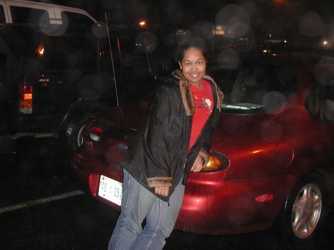
1993 Ford Taurus/
Photo
supermotors.net/registry/media/180962
Ford Taurus Cornering Lamps Wiring Diagram (Page 91-1) - Multi-Function Switch

Wiring diagram for cornering lamps showing the main light switch, multi-function switch and color-coded circuits.
This is page 91-1, "Cornering Lamps," from a Ford factory wiring diagram manual. It shows the cornering lamp circuit beginning at a hot-at-all-times feed through the Main Light Switch (fused at 22 A; switch positions OFF, PARK, HEAD; terminals B1, B3, H), with references to pages 13-22, 13-23, 13-24 and switch testing on page 149-1. Power leaves the switch on circuit 15 R/Y (red/yellow) through connector C2032 (12V in HEAD position), passes connector C212 with a branch to the Automatic Headlamps/Delayed Exit system (page 87-1), and continues on circuit 15 R/Y to connector C268 into the Multi-Function Switch (testing on page 149-7). The multi-function switch internal schematic shows the flash-to-pass, dimmer (HI/LO/PASS), and cornering (left turn/right turn) contacts, with output circuits 12, 527, 18, 507, 380 and 379. The cornering outputs exit at connector C269 as circuit 380 P/Y (pink/yellow, 12V LH turn) and circuit 379 BR/W (brown/white, 12V RH turn), pass through connector C100, and route to the left and right cornering lamps. Readers can learn the wire colors, circuit numbers, connector identities, and cross-reference page numbers for testing this circuit.
Is this accurate? Sign in to help verify it.
Frequently asked questions
- What wire color and circuit feeds the cornering lamps from the main light switch?
- Circuit 15, a red/yellow (R/Y) wire, hot at all times through the main light switch (22 A fuse), energized at 12V in the HEAD position through connectors C2032, C212 and C268.
- Which circuits control the left and right cornering lamps?
- Circuit 380 P/Y (pink/yellow) is the left turn cornering output and circuit 379 BR/W (brown/white) is the right turn cornering output, exiting the multi-function switch at connector C269 and passing through connector C100.
- Where can I find test procedures for the switches in this circuit?
- The diagram references page 149-1 for main light switch testing and page 149-7 for multi-function switch testing.
- What other system taps into the cornering lamp feed?
- At connector C212, circuit 15 R/Y branches to the Automatic Headlamps/Delayed Exit system, shown on page 87-1.
- What connectors are used in the cornering lamp circuit?
- Connectors C2032, C212, C268, C269 and C100 appear in this diagram.
Comments
More from this build





No comments yet.