1992 Ford Bronco Custom Bumper Mounting Bracket & Frame Reinforcement Diagram
Reference · 1992-1996 BroncoAll 95 schematics


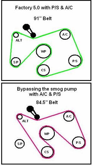
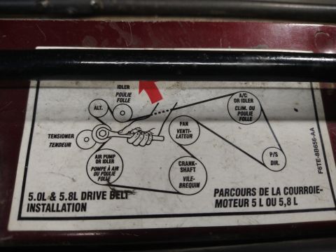
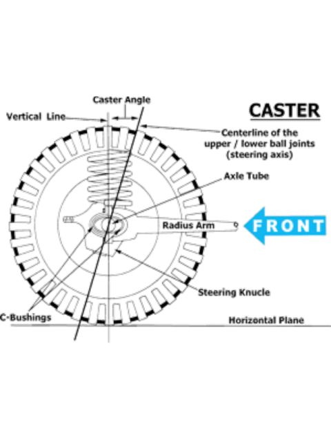









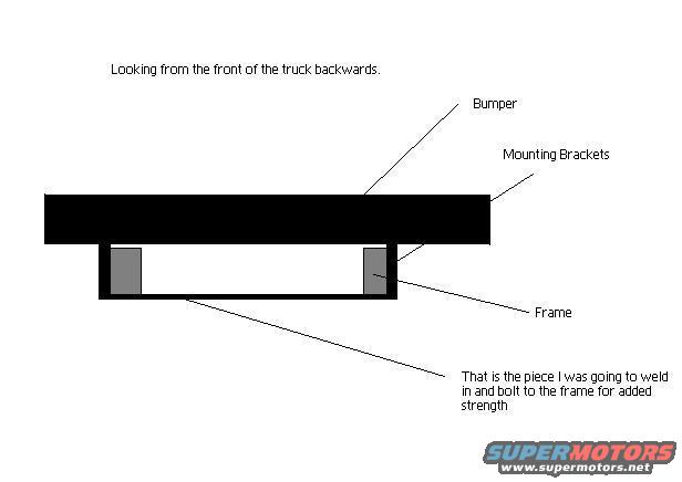
User-drawn schematic showing a bumper, mounting brackets and frame piece intended to be welded for added strength.
Part of 1992-1996 Ford Bronco Schematics
This is a simple homemade schematic drawing, uploaded to a 1992 Ford Bronco gallery, illustrating a custom bumper mounting plan. The view is described as "Looking from the front of the truck backwards." The drawing shows a large black horizontal bar labeled "Bumper" sitting on top of two gray vertical blocks labeled "Mounting Brackets," which attach to the vehicle's "Frame," drawn as an outlined channel below the bumper. A callout points to a horizontal piece spanning between the frame rails, annotated: "That is the piece I was going to weld in and bolt to the frame for added strength." The document contains no part numbers, dimensions, torque specifications, fuse information, or wire colors, it is purely a conceptual fabrication sketch. A reader can learn the intended arrangement of the custom bumper relative to the frame, where the mounting brackets sit, and that the builder planned to add a welded and bolted cross-piece to reinforce the frame at the bumper mount location. No year, make, or model is stated within the drawing itself; its association with a 1992 Ford Bronco comes solely from the uploader's gallery attribution.
Is this accurate? Sign in to help verify it.
Frequently asked questions
- What view does this bumper diagram show?
- It is drawn looking from the front of the truck backwards, showing the bumper, mounting brackets, and frame in cross-section.
- How does the bumper attach to the frame in this design?
- The bumper sits on mounting brackets that connect to the frame, with an additional piece to be welded in and bolted to the frame for added strength.
- What is the purpose of the extra piece shown between the frame rails?
- According to the annotation, it is a piece the builder was going to weld in and bolt to the frame for added strength.
- Does the diagram include dimensions or part numbers?
- No. The sketch only labels the bumper, mounting brackets, frame, and the reinforcement piece; no measurements, part numbers, or torque specs are given.






No comments yet.