Home/
Registry/
Ford/
Bronco/
1980-1986/
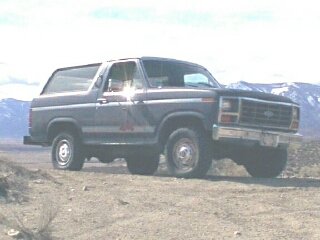
1984 Ford Bronco/
Photo
supermotors.net/registry/media/293055
Custom Crossmember Bracing Sketch - Frame & Mounting Point Diagram (Ford Bronco)

Reference · 1980-1986 BroncoAll 34 schematics
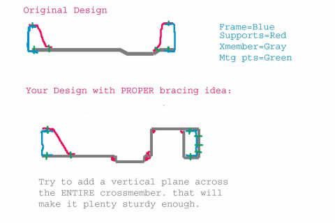
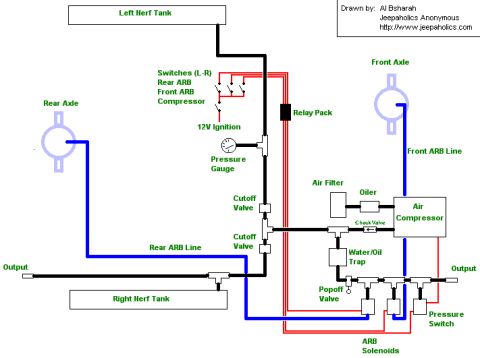
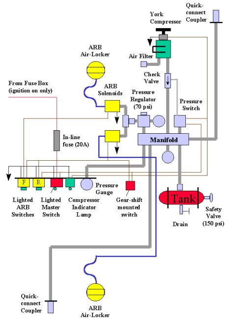
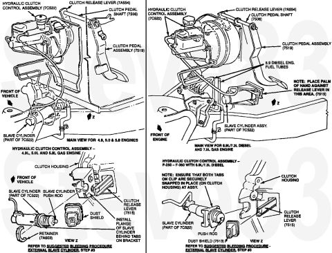
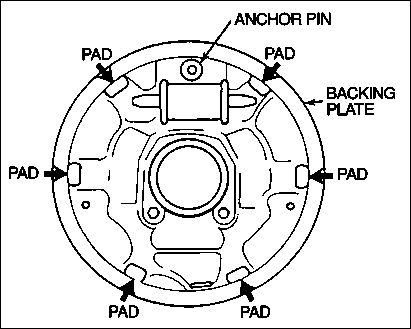
Structural schematic comparing original frame design to a braced version with color-coded frame, supports and crossmember.
Part of 1980-1986 Ford Bronco Schematics
This document is a hand-drawn digital sketch (not a factory schematic) comparing two crossmember designs, apparently shared as advice in an automotive forum context. The top drawing, labeled "Original Design," shows a simple, mostly flat crossmember spanning between two frame rails. The bottom drawing, labeled "Your Design with PROPER bracing idea," shows a modified crossmember with a stepped/dropped center section and an additional boxed section wrapping around the right frame rail. A color legend identifies the elements: the frame rails are drawn in blue, supports in red, the crossmember (Xmember) in gray, and mounting points in green. The accompanying note advises: "Try to add a vertical plane across the ENTIRE crossmember. that will make it plenty sturdy enough." A reader can learn the suggested approach for strengthening a custom crossmember, extending a full-length vertical plane across it rather than relying on the original flat design, and can see where the supports and mounting points attach relative to the frame rails. The document contains no year, make, model, part numbers, or dimensions; it was uploaded to a 1984 Ford Bronco gallery but does not itself state vehicle applicability.
Is this accurate? Sign in to help verify it.
Frequently asked questions
- What do the colors in the crossmember diagram mean?
- Per the legend: Frame = Blue, Supports = Red, Xmember (crossmember) = Gray, and Mtg pts (mounting points) = Green.
- What bracing improvement does the sketch recommend?
- It recommends adding a vertical plane across the ENTIRE crossmember, stating that this "will make it plenty sturdy enough."
- How many designs are compared in this document?
- Two: an "Original Design" flat crossmember, and a revised "Your Design with PROPER bracing idea" showing a stepped crossmember with added bracing around the frame rails.
- Does the document give dimensions, part numbers, or vehicle years?
- No. It is a conceptual sketch only, with a color legend and a bracing suggestion, but no measurements, part numbers, or stated vehicle applicability.
No comments yet.