Home/
Registry/
Ford/
Bronco/
1980-1986/
1984 Ford Bronco/
Photo
supermotors.net/registry/media/307088
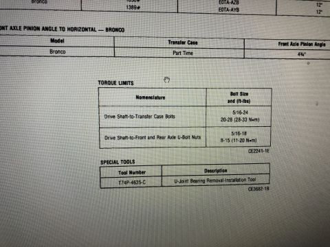
1984 Ford Bronco Pinion Angle Alignment Sketch - Driveline Diagram

Reference · 1980-1986 BroncoAll 34 schematics
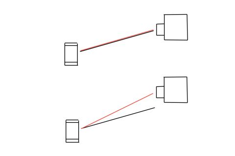

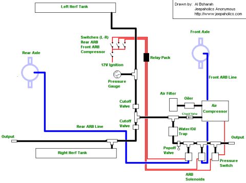




Simplified connection schematic showing red and black wires routed between a cylinder and a box-shaped component.
Part of 1980-1986 Ford Bronco Schematics
This document is an untitled, unlabeled hand-drawn schematic sketch, filed under a 1984 Ford Bronco and named 'pinion copy.jpg', which suggests it illustrates driveline/pinion angle alignment. The sketch contains two panels. Each panel shows a small rectangular component on the left (likely representing a pinion/differential end or transfer case output) and a larger boxy component with a small protrusion on the right (likely the transmission/transfer case or differential). In the top panel, a red line and a black line run essentially parallel and nearly overlapping between the two components, apparently depicting an aligned or correct condition. In the bottom panel, the red and black lines diverge noticeably, apparently depicting a misaligned or incorrect angle condition. There is no text, no dimensions, no angle values, no part numbers, and no legend anywhere in the image, so all interpretation beyond the visual geometry is inferred from the filename and context. A reader can learn only the conceptual visual contrast between an aligned case and a diverging-angle case; no specifications can be obtained from this document.
Is this accurate? Sign in to help verify it.
Frequently asked questions
- Does this diagram contain any angle measurements or specifications?
- No. The sketch contains no text, numbers, angle values, or specifications of any kind, only line drawings.
- What is the difference between the two panels in the sketch?
- In the top panel the red and black lines between the two components run nearly parallel/overlapping; in the bottom panel the red and black lines diverge at an angle, suggesting a comparison between an aligned and a misaligned condition.
- What do the red and black lines represent?
- The document itself does not label them. Visually, they are reference lines drawn between the small left component and the larger right component, overlapping in the first panel and diverging in the second.
- Are any part numbers or vehicle details shown in this document?
- No. There are no part numbers, vehicle identification, years, or model information visible anywhere in the image.






No comments yet.