Home/
Registry/
Ford/
Bronco/
1980-1986/
1984 Ford Bronco/
Photo
supermotors.net/registry/media/286620
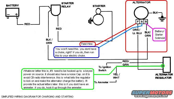
1984 Ford Bronco Simplified Charging & Starting Wiring Diagram - Wire Colors
Reference · 1980-1986 BroncoAll 92 wiring diagrams
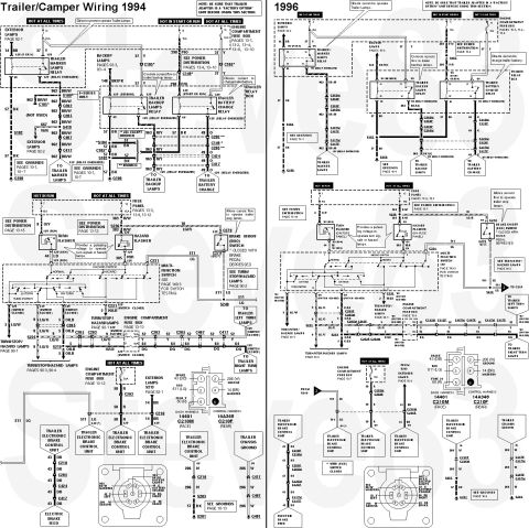
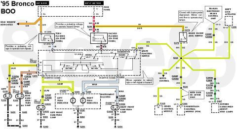
Wiring diagram for charging and starting showing battery, starter relay, alternator and regulator with color-coded wires.
Part of 1980-1986 Ford Bronco Wiring Diagrams
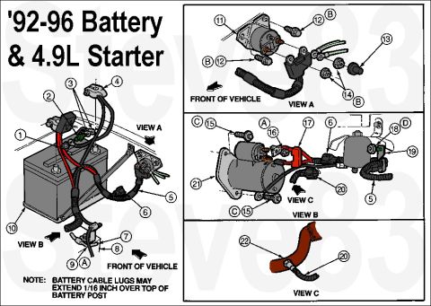
This document is a hand-drawn, simplified wiring diagram for the charging and starting system of a Ford vehicle, uploaded to the gallery of a 1984 Ford Bronco. It illustrates the connections between the battery, starter relay, starter, alternator, and alternator regulator. The battery positive terminal connects via a RED wire to the starter relay, which feeds the starter with another RED wire. The alternator has three labeled terminals: F (field wire, ORN/Lt. BLU noted nearby), S, and B (BLK/ORN to the battery/starter solenoid), plus a BLK wire to ground. The regulator connects via BLK/ORN, RED/GRN (to the ignition switch), and YEL/WHT (to the ammeter). Annotations explain that the field wire is only needed for an electric choke, and that one regulator wire must be connected to a keyed power source with a noise capacitor to prevent CB radio interference; this wire signals the regulator to activate charging. The author notes this connection can route through an ammeter if present. Readers can learn basic wire color codes and routing for a Ford external-regulator alternator charging and starting setup, though the diagram is informal and lacks specific terminal letters for the regulator, which the author promises to provide later.
Is this accurate? Sign in to help verify it.
Frequently asked questions
- What wire color goes from the battery to the starter relay?
- A RED wire runs from the battery positive terminal to the starter relay.
- What are the alternator terminal labels and their wire colors?
- The alternator has F, S, and B terminals. The F terminal is the field wire, ORN/Lt. BLU is noted near S, and B uses BLK/ORN to the battery/starter solenoid. A BLK wire goes to ground.
- What connects the alternator regulator to the ignition switch and ammeter?
- A RED/GRN wire goes to the ignition switch and a YEL/WHT wire goes to the ammeter.
- Is the field wire always needed?
- Per the diagram's note, the field wire isn't needed unless you have an electric choke, in which case it should be run to the choke.
- Why does one regulator wire need a noise capacitor?
- The diagram states the keyed-power wire to the regulator should have a noise cap to avoid CB radio interference; this wire tells the regulator to kick on so the alternator charges the battery.


No comments yet.