5 Wire Alternating 12V Positive Door Locks Relay Wiring Diagram (the12volt.com)
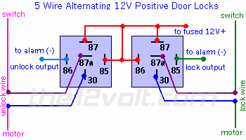
Wiring diagram showing two relays wired for 5-wire alternating 12V positive door locks with lock/unlock outputs to the motor.
This document is a wiring diagram titled "5 Wire Alternating 12V Positive Door Locks," hosted/watermarked by the12volt.com. It shows how to connect two standard 5-pin automotive relays (pins 30, 85, 86, 87, and 87a on each) to interface an alarm system's negative lock and unlock outputs with a vehicle's 5-wire alternating 12V positive door lock system. Each relay's pin 87 is fed from a fused 12V+ source (red wires). The alarm's negative unlock output (blue wire) triggers the left relay via pin 85/86, and the alarm's negative lock output triggers the right relay. Pin 30 of each relay connects to the unlock wire (purple) and lock wire (green) respectively, which run between the door lock switch and the door lock motors. The diagram indicates the switch connections at the top on both sides and the motor connections at the bottom. A reader can learn the relay pin assignments and wire routing needed to add aftermarket alarm/keyless-entry control to a positive-trigger 5-wire door lock system. The diagram is generic and does not state a specific vehicle make, model, or year.
Is this accurate? Sign in to help verify it.
Frequently asked questions
- How many relays are needed for 5 wire alternating 12V positive door locks?
- The diagram shows two 5-pin relays (with terminals 30, 85, 86, 87, and 87a), one for the unlock circuit and one for the lock circuit.
- What triggers the relays in this diagram?
- The alarm's negative (-) outputs: one relay is triggered by the alarm's unlock output and the other by the alarm's lock output.
- Where does power for the relays come from?
- Pin 87 of each relay connects to a fused 12V+ source, shown as red wires in the diagram.
- Which relay pins connect to the door lock wires?
- Pin 30 of each relay connects into the lock/unlock wires, the unlock wire (purple) on one relay and the lock wire (green) on the other, between the switch and the motors.
Comments
More from this build






No comments yet.