Reverse Polarity Door Lock Actuator Relay Wiring Diagram - 2 Relay Setup
Reference · 1992-1996 BroncoAll 411 wiring diagrams
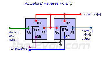
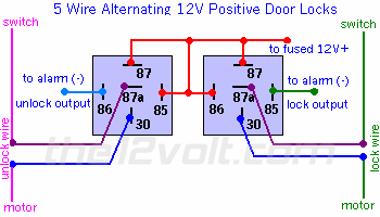
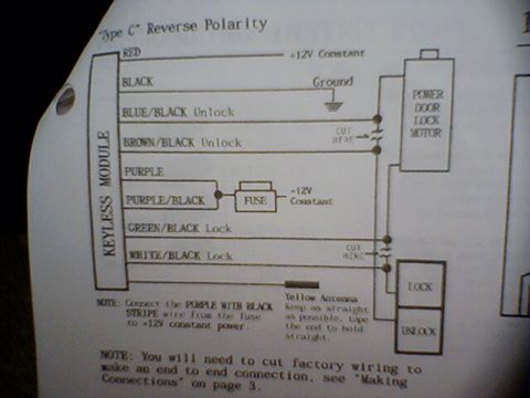
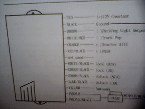












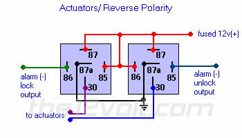
Wiring diagram of two relays configured for reverse-polarity actuators showing terminal numbers and fused 12V supply to the actuators.
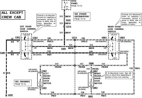
Part of 1992-1996 Ford Bronco Wiring Diagrams
This document is a wiring diagram titled "Actuators / Reverse Polarity" showing how to wire two standard 5-pin automotive relays (pins 30, 85, 86, 87, 87a) to drive door lock actuators with reversed polarity from an alarm system's negative outputs. A fused 12V(+) source (red wire) feeds pin 87 of both relays. Pin 87a of each relay is connected to chassis ground. The alarm's negative lock output (green wire) triggers pin 86 of the left relay, and the alarm's negative unlock output (blue wire) triggers pin 86 of the right relay; pins 85 tie into the circuit to complete the relay coils. Pin 30 of each relay runs to the door lock actuators, so energizing one relay or the other reverses the polarity across the actuator motors, driving them to lock or unlock. The diagram was uploaded to a 1994 Ford Bronco gallery alongside other door-lock wiring documents, and appears to originate from the12volt.com based on the watermark. A reader can learn the relay pin connections needed to convert single-polarity alarm outputs into reverse-polarity actuator control.
Is this accurate? Sign in to help verify it.
Frequently asked questions
- How many relays are needed to wire door lock actuators for reverse polarity?
- The diagram uses two relays, each with pins 30, 85, 86, 87, and 87a.
- Where does the fused 12V(+) wire connect in this diagram?
- The fused 12v(+) supply (red wire) connects to pin 87 of both relays.
- Which relay pins connect to the alarm outputs?
- The alarm (-) lock output connects to pin 86 of one relay, and the alarm (-) unlock output connects to pin 86 of the other relay.
- Which relay pin goes to the actuators?
- Pin 30 of each relay is wired to the actuators.
- Are the alarm lock/unlock outputs positive or negative in this diagram?
- They are negative (-) outputs, labeled 'alarm (-) lock output' and 'alarm (-) unlock output'.






No comments yet.