Ford Bronco/F-Series Power Door Lock Wiring Diagram - All Except Crew Cab

Reference · 1992-1996 BroncoAll 411 wiring diagrams
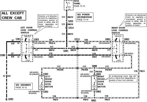












Wiring diagram of the power door lock motor circuits (all except crew cab) with color-coded wires, connectors and grounds.
Part of 1992-1996 Ford Bronco Wiring Diagrams
This is a Ford power door lock wiring diagram labeled "ALL EXCEPT CREW CAB." It shows the complete circuit for the power door lock system: power feeds from fuse panel fuse 12 (a 20A circuit breaker, referenced to Fuse Panel page 13-13 and Power Distribution page 13-14) on circuit 171 BK/W through splice S222 and connectors C214/C213 to splice S501, feeding both the left door lock control switch (connector C503) and right door lock control switch (connector C603). The switches are bi-directional, supplying momentary ground or power to either side of the door lock motors. Circuit 120 PK/LG carries 12V in UNLOCK; circuit 119 PK/Y carries 12V in LOCK. Circuit 117 PK/BK (12V lock / 0V unlock) and circuit 118 PK/O (12V unlock / 0V lock) connect to the left front door lock motor (C502) and right front door lock motor (C602), through splices S600 and S601. Ground is circuit 57 BK through splice S500 to ground G201 (Grounds page 10-12). The diagram includes voltage test values at each pin for lock and unlock switch positions, making it useful for diagnosing inoperative or one-sided door lock failures.
Is this accurate? Sign in to help verify it.
Frequently asked questions
- What fuse powers the power door locks in this diagram?
- Fuse 12 in the fuse panel, a 20A circuit breaker (CB), referenced to Fuse Panel page 13-13.
- What wire colors are used for the door lock circuits?
- Circuit 171 is BK/W (power feed), 120 is PK/LG (unlock, 12V in unlock), 119 is PK/Y (lock, 12V in lock), 117 is PK/BK (12V lock / 0V unlock), 118 is PK/O (12V unlock / 0V lock), and 57 is BK (ground).
- How do the door lock switches work?
- Each switch controls a bi-directional motor by supplying a momentary ground or power to either side of the motor depending on the switch position.
- Where does the door lock system ground?
- Through circuit 57 BK via splice S500 to ground G201 (see Grounds page 10-12).
- Which connectors serve the door lock motors and switches?
- Left door lock control switch: C503; right door lock control switch: C603; left front door lock motor: C502; right front door lock motor: C602.






No comments yet.