Home/
Registry/
Ford/
Bronco/
1987-1991/
1991 Ford Bronco/
Photo
supermotors.net/registry/media/408214
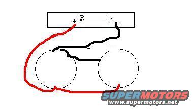
1991 Ford Bronco Speaker Wiring Sketch - R/L Channel to Dual Speakers Diagram
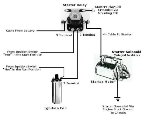
Reference · 1987-1991 BroncoAll 175 wiring diagrams

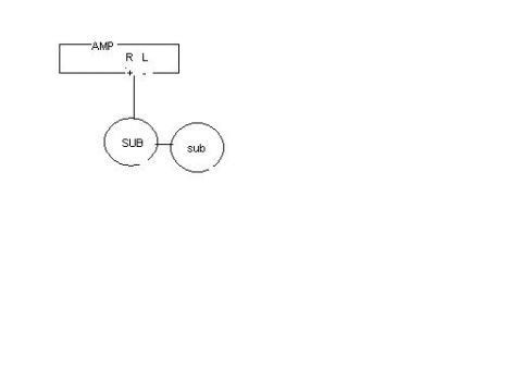













Speaker wiring diagram with color-coded positive and negative leads from R/L terminals to two speakers.
Part of 1987-1991 Ford Bronco Wiring Diagrams
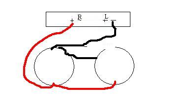
This document is a simple hand-drawn (computer-sketched) speaker wiring diagram, apparently showing how to wire two round speakers to a two-channel audio source or amplifier. The rectangular box at the top represents the head unit or amp, with right-channel terminals marked "R" (+ and -) and left-channel terminals marked "L" (+ and -). Two circles below represent the speakers. A black wire runs from the left-channel terminal down to the left speaker, and a straight black line bridges the two speakers together, suggesting a series or shared connection between them. A red wire runs from the right-channel positive terminal around the outside of the drawing to the right speaker. The diagram was uploaded to a 1991 Ford Bronco gallery alongside another wiring scan, and likely illustrates a custom audio/speaker hookup (possibly bridging or series-wiring two speakers across the stereo's R and L channels). No wire gauges, colors codes beyond the red/black drawing colors, part numbers, or vehicle-specific labels appear, so the reader learns only the general connection topology: R and L channel terminals feeding two interconnected speakers via red and black leads.
Is this accurate? Sign in to help verify it.
Frequently asked questions
- What does this diagram show?
- A hand-drawn sketch of two round speakers wired to a box with right (R) and left (L) channel terminals, each marked + and -.
- How are the two speakers connected to each other?
- A straight black line connects the two speakers directly to one another, indicating they are wired together (e.g., in series or sharing a connection).
- Which wire colors are used in the diagram?
- A red wire runs from the R + terminal around to the right speaker, and a black wire runs from the L terminal area to the left speaker.
- Does the diagram list wire gauges or part numbers?
- No. The only text visible is the terminal labels R, L, +, and -; no gauges, colors codes, or part numbers are given.






No comments yet.