Ford COP Ignition Coil Harness Connector Pinout Diagram - 1998 Taurus

Coil-On-Plug ignition coil harness connector diagram showing the two pins (IGN Start/Run and CD/coil driver); test pins located on breakout box, connectors viewed into mating surface.
This document is a wiring/connector diagram for a Coil On Plug (COP) ignition coil harness connector. It shows a two-pin connector illustration with two circuits routed to it: one labeled "IGN START/RUN" (ignition power feed active in Start/Run) and one labeled "CD" (coil driver signal), with a note directing the reader to "see chart for *test pin #." Footnotes clarify that the asterisked test pins are located on a breakout box and that all harness connectors are viewed looking into the mating surface. The diagram is useful for technicians probing the COP ignition coil connector during diagnostics: it identifies which terminal receives ignition voltage and which carries the coil driver (CD) signal from the PCM, and it establishes the correct pin orientation for testing. The document itself contains no year, make, model, engine, wire color, or part number information; it was uploaded to a 1998 Ford Taurus gallery alongside related PCM and powertrain diagram scans, so applicability to that vehicle is a claim by the uploader rather than something stated in the image.
Is this accurate? Sign in to help verify it.
Frequently asked questions
- What connector does this diagram show?
- The Coil On Plug (COP) ignition coil harness connector, drawn as a two-pin connector viewed into its mating surface.
- What circuits go to the COP ignition coil connector?
- Two circuits: IGN START/RUN (ignition power in Start/Run) and CD (coil driver signal).
- Where are the referenced test pins located?
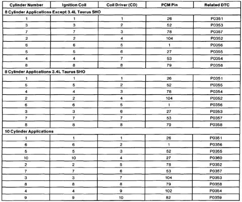
- Per the footnote, the *test pins are located on a breakout box; a separate chart lists the test pin numbers.
- How are the harness connectors viewed in this diagram?
- All harness connectors are viewed looking into the mating surface, per the footnote.
Comments
More from this build

No comments yet.