Ford Pinpoint Test JF7-JF11: Coil Driver (CD) Circuit & Ignition Coil Diagnosis

Reference · 1996-1999 TaurusAll 18 service procedures
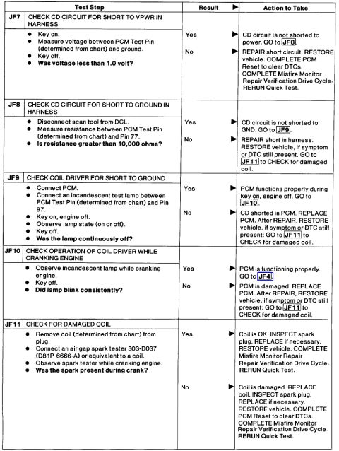
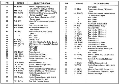
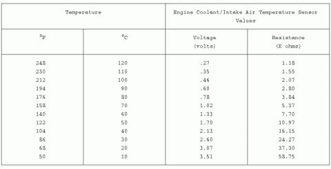



Coil-On-Plug pinpoint test (JF7-JF11): verify CD circuit not shorted to VPWR (<1.0V) or ground (>10,000 ohms between PCM test pin and Pin 77), check coil driver and damaged coil.
Part of 1996-1999 Ford Taurus Service Procedures
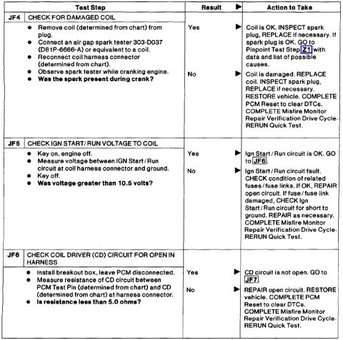
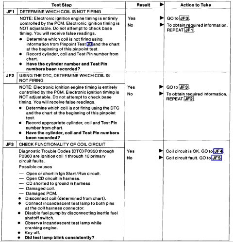
This document is one page of a Ford pinpoint diagnostic test procedure (steps JF7 through JF11) for troubleshooting the ignition coil driver (CD) circuit between the PCM and the ignition coils. Each step is laid out in a table with a Test Step column, a Yes/No Result column, and an Action to Take column. JF7 checks the CD circuit for a short to vehicle power (VPWR) in the harness by measuring voltage at the PCM test pin. JF8 checks the CD circuit for a short to ground by measuring resistance to Pin 77 (looking for greater than 10,000 ohms). JF9 checks the coil driver inside the PCM for a short to ground using an incandescent test lamp between the PCM test pin and Pin 97. JF10 verifies coil driver operation while cranking the engine by watching for consistent lamp blinking. JF11 checks for a damaged coil using an air gap spark tester 303-D037 (D81P-6666-A) while cranking. Failing results lead to repairing the harness short, replacing the PCM, or replacing the coil, followed by restoring the vehicle, completing a PCM reset to clear DTCs, completing the Misfire Monitor Repair Verification Drive Cycle, and rerunning the Quick Test.
Is this accurate? Sign in to help verify it.
Frequently asked questions
- How do I check the CD circuit for a short to power (JF7)?
- With the key on, measure voltage between the PCM test pin (determined from chart) and ground, then key off. If voltage is less than 1.0 volt, the CD circuit is not shorted to power and you go to JF8; if not, repair the short circuit, restore the vehicle, complete a PCM Reset to clear DTCs, complete the Misfire Monitor Repair Verification Drive Cycle, and rerun the Quick Test.
- What resistance indicates the CD circuit is not shorted to ground in step JF8?
- With the scan tool disconnected from the DCL, measure resistance between the PCM test pin and Pin 77. If resistance is greater than 10,000 ohms, the CD circuit is not shorted to ground and you proceed to JF9.
- What tool is used in JF11 to check for a damaged coil?
- An air gap spark tester 303-D037 (D81P-6666-A) or equivalent is connected to the coil, and the spark tester is observed while cranking the engine. No spark during crank means the coil is damaged and must be replaced.
- What happens if the test lamp is not continuously off in step JF9?
- The CD is shorted in the PCM. Replace the PCM; after repair, restore the vehicle, and if the symptom or DTC is still present, go to JF11 to check for a damaged coil.
- What should be done after replacing a damaged coil per JF11?
- Inspect the spark plug and replace if necessary, restore the vehicle, complete a PCM Reset to clear DTCs, complete the Misfire Monitor Repair Verification Drive Cycle, and rerun the Quick Test.



No comments yet.