Ford PCM Connector Pinout Diagram Pins 35-90 - Circuits & Wire Colors

PCM connector pinout (pins 35-90) with circuit numbers/colors: HO2S 11/12/21/22, MAF, ECT, IAT, TFT sensors, COP #2/#4/#5/#7, fuel injectors 1-6, EGR/EVR, knock sensors.
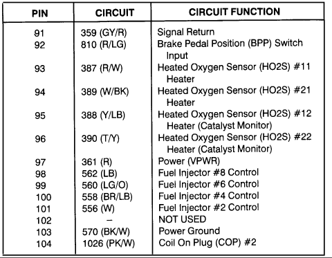
This document is a PCM (Powertrain Control Module) connector pinout table covering pins 35 through 90, showing for each pin its circuit number, wire color code, and circuit function. It appears to be the second page of a two-page pinout set (filename PCM2.gif, following PCM1.gif). Readers can identify which PCM pin connects to key engine management circuits, including heated oxygen sensors (HO2S #11, #12, #21, #22), Mass Air Flow sensor input and return, Engine Coolant Temperature, Intake Air Temperature, Throttle Position, Camshaft Position, Knock Sensor #1, Fuel Tank Pressure, and DPFE EGR sensors. Output/control circuits listed include fuel injectors #1, #3, #5, and #7, Coil On Plug drivers #4, #5, #7, and #8, fuel pump relay, A/C clutch relay, high speed cooling fan relay, EGR vacuum regulator, EVAP canister purge and vent, Idle Air Control valve, Torque Converter Clutch solenoid, and Electronic Pressure Control solenoid. Power and ground circuits (VPWR pin 71, Keep Alive Power pin 55, and Power Grounds on pins 51, 76, 77, circuit 570 BK/W) and reference voltage (pin 90) are also identified. Several pins (43, 44, 49, 50, 63, 66-68, 82, 84) are marked NOT USED. The presence of injector #7 and COP #8 indicates a V8 application.
Is this accurate? Sign in to help verify it.
Frequently asked questions
- Which PCM pins are power grounds?
- Pins 51, 76, and 77 are Power Ground, all using circuit 570 (BK/W).
- What pin is the Throttle Position (TP) sensor input on the PCM?
- Pin 89, circuit 355 (GY/W), is the Throttle Position (TP) Sensor Input.
- What is the wire color for the Fuel Pump Relay Control at the PCM?
- Pin 80 uses circuit 926 with a light blue/orange (LB/O) wire for Fuel Pump Relay Control.
- Which pin provides Keep Alive Power (B+) to the PCM?
- Pin 55, circuit 1076 (DG/O), is Keep Alive Power (B+).
- Which PCM pins are not used?
- Pins 43, 44, 49, 50, 63, 66, 67, 68, 82, and 84 are marked NOT USED.
Comments
More from this build




No comments yet.