Home/
Registry/
Suzuki/
Samurai/
1986-1995/
“Little Blue”/
Photo
supermotors.net/registry/media/420632
Suzuki Samurai/Sidekick RWAL Anti-Lock Brake Wiring Diagram - Fuses & Grounds
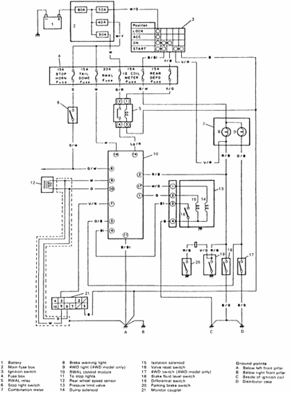
Factory wiring diagram showing the fuse box, ignition switch, relays, sensors and solenoids with a numbered component and ground-point legend.
This document is a factory-style wiring diagram for a Suzuki Rear Wheel Anti-Lock (RWAL) brake system, uploaded as page 1 of a two-page 'Antilock' set. It traces power from the battery through the main fuse box (60A, 50A, 40A, and 30A fuses) and the ignition switch (with a LOCK/ACC/ON/START contact table) to the interior fuse box, which contains the 15A STOP HORN, 15A TAIL DOME, 20A RWAL, 15A IG COIL METER, and 15A REAR DEFO fuses. From there the diagram shows the RWAL relay, stop light switch, RWAL control module (with numbered connector pins), rear wheel speed sensor, and the pressure limit valve assembly containing the dump solenoid, isolation solenoid, and valve reset switch. Warning-lamp circuits through the combination meter (brake warning light and 4WD light on 4WD models) are shown, along with the 4WD switch, brake fluid level switch, differential switch, parking brake switch, and a numbered monitor coupler used for diagnostics. Wire colors (e.g., W/G, B/Bl, Lg/R, V/R, G/W, R/B) are labeled throughout, and a legend identifies all 21 numbered components. Four chassis ground points are defined: below the left and right front pillars, beside the ignition coil, and at the distributor case.
Is this accurate? Sign in to help verify it.
Frequently asked questions
- What fuse protects the RWAL anti-lock brake system?
- The diagram shows a 20A RWAL fuse in the fuse box, alongside the 15A STOP HORN, 15A TAIL DOME, 15A IG COIL METER, and 15A REAR DEFO fuses.
- What main fuses are shown in the main fuse box?
- The main fuse box near the battery contains 60A, 50A, 40A, and 30A fuses.
- What components make up the RWAL system in this diagram?
- Battery, main fuse box, ignition switch, fuse box, RWAL relay, stop light switch, combination meter (brake warning light and 4WD light), RWAL control module, rear wheel speed sensor, pressure limit valve with dump solenoid, isolation solenoid and valve reset switch, 4WD switch, brake fluid level switch, differential switch, parking brake switch, and a monitor coupler.
- Where are the ground points for this circuit located?
- Ground point A is below the left front pillar, B is below the right front pillar, C is beside the ignition coil, and D is at the distributor case.
- Which components apply only to 4WD models?
- The 4WD light (item 9) and the 4WD switch (item 17) are noted as '4WD model only'.
Comments
More from this build














No comments yet.