Home/
Registry/
Suzuki/
Samurai/
1986-1995/
“Little Blue”/
Photo
supermotors.net/registry/media/420643
Suzuki Samurai CMP Sensor (Distributor) Wiring Diagram - ECM Pin B3 Vout
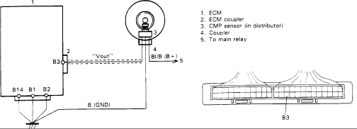
Factory wiring diagram showing the camshaft position sensor and ECM coupler wiring with the B3 connector terminal pinout view.
This document is a wiring diagram for a camshaft position (CMP) sensor circuit, showing how the sensor (located in the distributor) connects to the ECM. The diagram depicts the ECM as a large box with terminal B3 carrying the "Vout" signal line to the CMP sensor through a coupler (connector). A Bl/B (blue/black) wire supplies battery-positive (B+) power to the sensor circuit from the main relay. ECM terminals B14, B1, and B2 are shown tied together to a common chassis ground, labeled B (GND). A numbered legend identifies the five callouts: 1. ECM, 2. ECM coupler, 3. CMP sensor (in distributor), 4. Coupler, and 5. To main relay. A separate inset at the lower right shows the physical pin layout of the ECM coupler with the location of terminal B3 marked. A reader can learn the signal path (Vout on ECM pin B3), the power source (main relay via the Bl/B wire), the ground terminals (B14, B1, B2), and where to probe the ECM connector when diagnosing the CMP/crank sensor circuit. The scan was uploaded to a 1986 Suzuki Samurai gallery as part of a larger factory wiring-diagram set.
Is this accurate? Sign in to help verify it.
Frequently asked questions
- Where is the CMP sensor located according to this diagram?
- The legend states the CMP sensor is located in the distributor (item 3).
- Which ECM terminal carries the CMP sensor signal?
- ECM terminal B3 carries the "Vout" signal line to the CMP sensor.
- What powers the CMP sensor circuit?
- A Bl/B (blue/black) wire labeled B+ runs to the main relay (item 5), which supplies power to the circuit.
- Which ECM terminals are grounded in this circuit?
- ECM terminals B14, B1, and B2 are shown joined together and connected to chassis ground, labeled B (GND).
- What do the numbered callouts in the diagram mean?
- 1 = ECM, 2 = ECM coupler, 3 = CMP sensor (in distributor), 4 = Coupler, 5 = To main relay.
Comments
More from this build














No comments yet.