Home/
Registry/
Suzuki/
Samurai/
1986-1995/
“Little Blue”/
Photo
supermotors.net/registry/media/420633
Suzuki Brake & 4WD Warning Light Wiring Diagram - Combination Meter Circuit
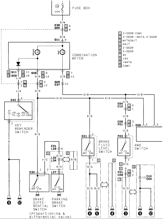
Factory wiring diagram routing the combination meter to brake-differential, parking-brake, brake-fluid-level and 4WD switches with wire color codes.
This scanned wiring diagram shows the brake and 4WD warning indicator circuit for a Suzuki vehicle. Power originates at fuse 18 (15A) in the fuse box and feeds through a Black/White (B/W) wire via connectors E38/G05 and G11 to the combination meter, which contains the BRAKE and 4WD indicator lamps. From the meter, circuits branch through connectors G09/G11, G06/E37, E54/C10, C08/P01, and E56 to several switches: a key reminder switch (E42, positions ST/IG2/IG1/ACC/LOCK), a brake fluid level switch (E21), a 4WD switch (P03), a brake differential switch (E30, labeled 'proportioning & differential valve'), and a parking brake switch (L27). Wire colors identified include B/W, V/R, R/B, O/B, B, B/G, and V/G. A numbered legend (1–10) keys circuit variations to body/build configurations: 2-door vs. 4-door, CAMI vs. IWATA assembly, M/T & 3A/T vs. 4A/T transmissions, and 8V vs. 16V engines. Connector pin numbers and ground points are marked throughout. A reader can trace the warning-lamp grounding paths for the brake fluid level, parking brake, differential valve, and 4WD indicator circuits, and identify which wiring variant applies to their specific configuration.
Is this accurate? Sign in to help verify it.
Frequently asked questions
- What fuse powers the brake and 4WD warning light circuit in this diagram?
- Fuse 18, a 15A fuse in the fuse box, feeds the circuit through a Black/White (B/W) wire to the combination meter.
- Which switches are shown in this warning light wiring diagram?
- The key reminder switch (E42), brake fluid level switch (E21), 4WD switch (P03), brake differential switch (E30, part of the proportioning & differential valve), and parking brake switch (L27).
- What wire colors are used in this circuit?
- B/W (black/white) from the fuse box, V/R, R/B, O/B, B/G, V/G, and plain B (black) for grounds.
- What do the numbered legend boxes on the diagram mean?
- They indicate configuration-specific wiring: 1 = 2-door CAMI, 2 = 2-door IWATA and 4-door, 3 = M/T & 3A/T, 4 = 4A/T, 5 = 2-door, 6 = 4-door, 7 = 8V, 8 = 16V, 9 = IWATA, 10 = CAMI.
- What connectors link the combination meter to the switches?
- Connectors shown include E38/G05, G11, G09, G06/E37, E54/C10, C08/P01, E56, plus switch connectors E21, P03, E30, E31/L28, L32/L34, and L27.
Comments
More from this build














No comments yet.