Home/
Registry/
Suzuki/
Samurai/
1986-1995/
“Little Blue”/
Photo
supermotors.net/registry/media/420634
Suzuki A/T Shift Lock & Illumination Wiring Diagram - Shift Lock Relay/Solenoid
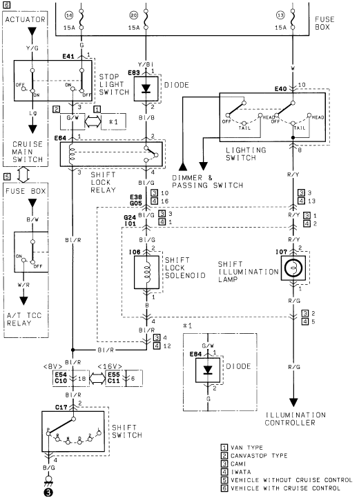
Factory wiring diagram of the shift-lock relay and solenoid, stop-light switch, lighting switch and shift illumination circuits with connector codes.
This scanned wiring diagram shows the automatic transmission shift lock and related circuits for a Suzuki vehicle. Power comes from three 15A fuses (positions 14, 20, and 13) in the fuse box. The diagram traces the stop light switch circuit through a diode (E83) to the shift lock relay (E64), which controls the shift lock solenoid (I06). It also shows the lighting switch (E40) with OFF/TAIL/HEAD positions feeding the dimmer & passing switch and the shift illumination lamp (I07), whose output continues to an illumination controller. Cruise-control-equipped vehicles route through the cruise main switch (E41) and actuator, while vehicles without cruise control use the A/T TCC relay via the fuse box. The shift switch (C17) shows gear positions P, R, N, D, 2, L and grounds through a B/G wire. Wire colors identified include Y/G, LG, G/W, Y/Bl, Bl/B, Bl/G, Bl/R, B/W, W/R, R/Y, R/G, B, and B/G. Connector/component codes include E38/G05, G24/I01, E54/C10, E55/C11, and E84 (diode). A legend distinguishes van type, canvastop type, CAMI vs. IWATA production plants, and vehicles with or without cruise control. A footnote (*1) shows an additional diode circuit (E84) for certain variants.
Is this accurate? Sign in to help verify it.
Frequently asked questions
- What fuses power the automatic transmission shift lock circuit in this diagram?
- Three 15A fuses in the fuse box, at positions 14, 20, and 13.
- What wire color feeds the shift lock solenoid (I06)?
- A Bl/G (blue/green) wire feeds terminal 1 of the shift lock solenoid; terminal 2 exits on a B (black) wire to pin 4, then continues as Bl/R.
- What components are in the shift lock circuit?
- The stop light switch, diode E83, shift lock relay E64, shift lock solenoid I06, shift switch C17 (positions P, R, N, D, 2, L), and for some variants diode E84 (*1).
- How is the shift illumination lamp wired?
- The lighting switch (E40) output on an R/Y wire feeds pin 1 of the shift illumination lamp (I07); pin 2 exits on an R/G wire that runs to the illumination controller.
- What do the numbered legend boxes mean?
- [1] Van type, [2] Canvastop type, [3] CAMI, [4] IWATA, [5] vehicle without cruise control, [6] vehicle with cruise control — indicating which circuit branches apply to each variant.
Comments
More from this build














No comments yet.