Home/
Registry/
Suzuki/
Samurai/
1986-1995/
“Little Blue”/
Photo
supermotors.net/registry/media/420659
Suzuki Samurai EGR / EGRT Sensor Schematic - California Spec ECM Wiring Diagram
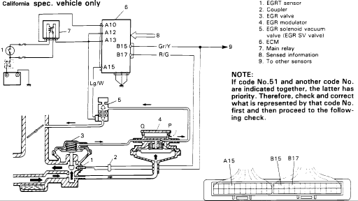
Schematic of the California-spec EGR system with EGRT sensor and ECM, including a connector pinout and diagnostic note.
Part of 1986-1995 Suzuki Samurai Schematics
This document is a schematic diagram for the EGR (Exhaust Gas Recirculation) system with EGRT (EGR temperature) sensor, applicable to California specification vehicles only. The diagram shows the physical and electrical layout of the EGR system components: the EGRT sensor (1), coupler (2), EGR valve (3), EGR modulator with ports P and Q (4), EGR solenoid vacuum valve/EGR SV valve (5), ECM (6), and main relay (7), along with sensed information inputs (8) and connections to other sensors (9). ECM connector terminals are identified, including A10, A12, A13, A15, B15, and B17, with wire colors noted: Gr/Y (gray/yellow) at B15, R/G (red/green) at B17, and Lg/W (light green/white) at A15 leading to the EGR solenoid vacuum valve. An inset at lower right shows the ECM connector face with pins A15, B15, and B17 located. A note explains diagnostic priority: if trouble code No. 51 appears together with another code, the other code takes priority and should be checked and corrected first before performing this system's check. This is useful for diagnosing EGR temperature sensor and EGR solenoid circuit faults.
Is this accurate? Sign in to help verify it.
Frequently asked questions
- What vehicles does this EGR/EGRT sensor schematic apply to?
- The document states it applies to California spec. vehicles only.
- What components are shown in this EGR system diagram?
- The legend lists: 1. EGRT sensor, 2. Coupler, 3. EGR valve, 4. EGR modulator, 5. EGR solenoid vacuum valve (EGR SV valve), 6. ECM, 7. Main relay, 8. Sensed information, and 9. To other sensors.
- Which ECM terminals and wire colors are used in this circuit?
- The diagram shows ECM terminals A10, A12, A13, A15, B15, and B17. Wire colors shown are Gr/Y at B15, R/G at B17, and Lg/W at A15 (to the EGR solenoid vacuum valve).
- What should I do if code No. 51 appears along with another trouble code?
- Per the note, if code No. 51 and another code are indicated together, the other code has priority. Check and correct what that code represents first, then proceed to this check.
Comments
More from this build














No comments yet.