Home/
Registry/
Suzuki/
Samurai/
1986-1995/
“Little Blue”/
Photo
supermotors.net/registry/media/420658
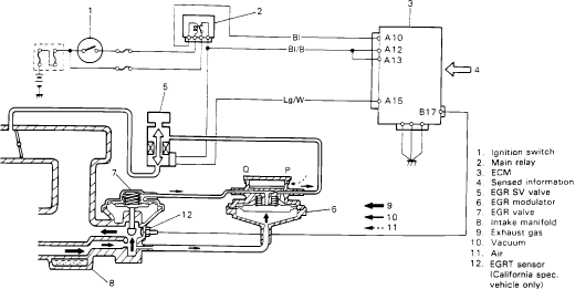
Suzuki Samurai EGR System Schematic - ECM, EGR Valve, Modulator & Wiring Diagram
Reference · 1986-1995 SamuraiAll 18 schematics



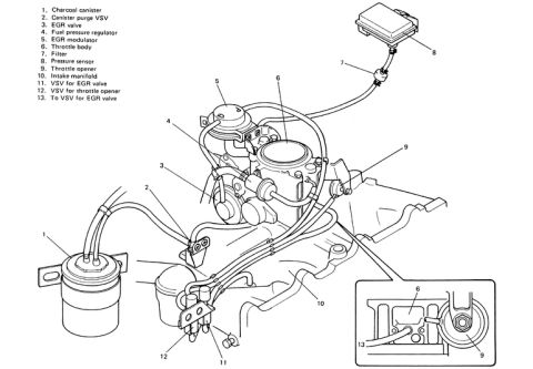
Schematic of the EGR emissions system showing the EGR valve, modulator and solenoid vacuum valve plumbing to the ECM with a numbered component legend.
Part of 1986-1995 Suzuki Samurai Schematics
This document is a schematic diagram of the Exhaust Gas Recirculation (EGR) system, uploaded to a 1986 Suzuki Samurai gallery on SuperMotors.net. The diagram shows the electrical and vacuum relationships between the ignition switch (1), main relay (2), and the ECM (3), which receives sensed information (4) and controls the EGR SV valve (5). The ECM connector pins involved are A10, A12, A13, A15, and B17, with wire colors Bl (blue), Bl/B (blue/black), and Lg/W (light green/white) identified on the circuit paths. The vacuum side of the diagram shows the EGR modulator (6, with ports labeled Q and P), the EGR valve (7), and the intake manifold (8). Flow arrows in the legend distinguish exhaust gas (9), vacuum (10), and air (11). Item 12 is the EGRT (EGR temperature) sensor, which the legend notes applies to California-specification vehicles only. A reader can learn how the ECM electrically controls the EGR solenoid vacuum valve, which wires and ECM pins are used, and how vacuum, air, and exhaust gas are routed through the modulator and EGR valve into the intake manifold.
Is this accurate? Sign in to help verify it.
Frequently asked questions
- Which ECM connector pins are used in the Suzuki Samurai EGR circuit?
- The diagram shows ECM pins A10, A12, A13, A15, and B17 connected in the EGR system circuit.
- What wire colors are used in the EGR control circuit?
- The diagram labels three wire colors: Bl (blue) to ECM pin A10, Bl/B (blue/black), and Lg/W (light green/white) to ECM pin A15.
- What components make up the EGR system in this schematic?
- The legend lists the ignition switch, main relay, ECM, sensed information, EGR SV valve, EGR modulator, EGR valve, intake manifold, and EGRT sensor, plus flows of exhaust gas, vacuum, and air.
- Is the EGRT sensor used on all vehicles?
- No. According to the legend, item 12, the EGRT sensor, is for California specification vehicles only.
- What controls the EGR SV valve?
- Per the diagram, the ECM (item 3) controls the EGR SV valve (item 5), with power supplied through the ignition switch and main relay.

No comments yet.