Home/
Registry/
Suzuki/
Samurai/
1986-1995/
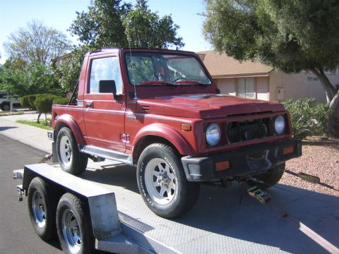
“Little Blue”/
Photo
supermotors.net/registry/media/420711
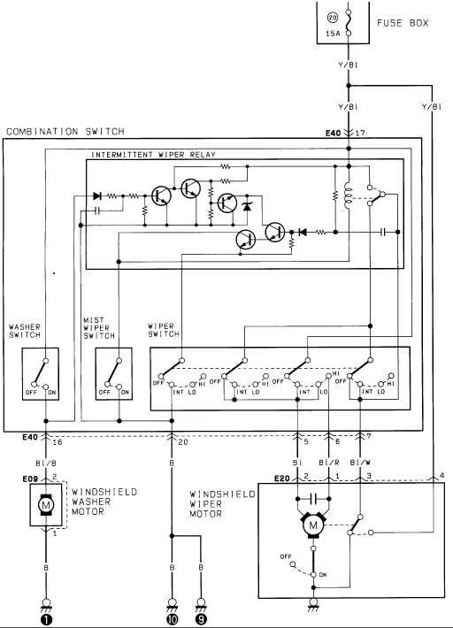
Suzuki Samurai Wiper & Washer Motor Wiring Diagram - Intermittent Relay Circuit
Reference · 1986-1995 SamuraiAll 73 wiring diagrams
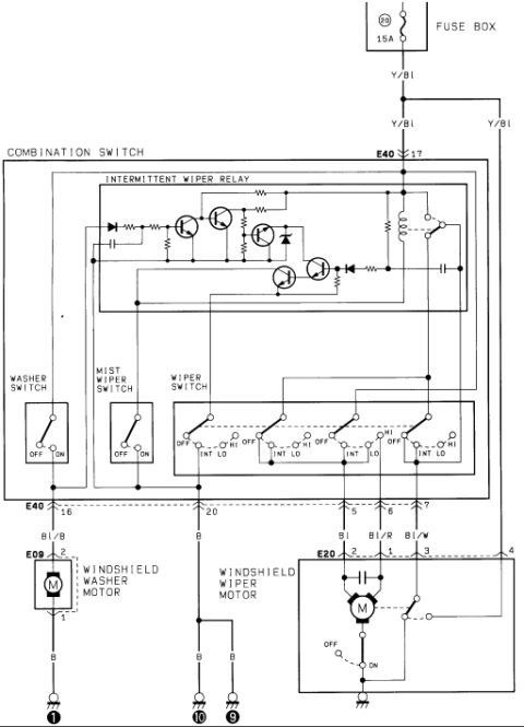
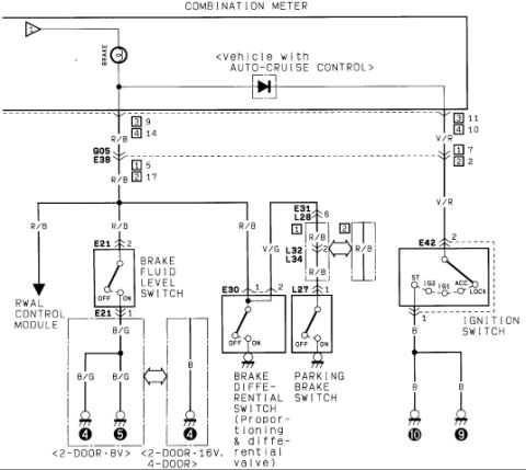
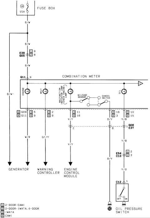
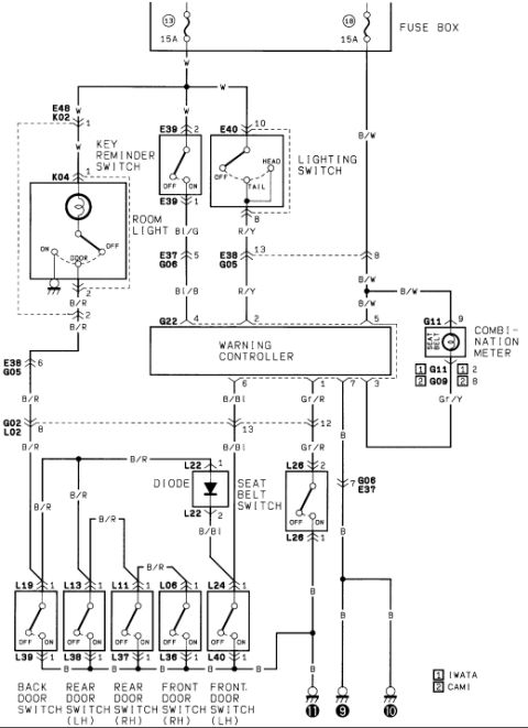
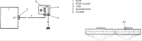

Wiring diagram of the windshield wiper and washer system showing the combination switch, intermittent wiper relay, and motors.
Part of 1986-1995 Suzuki Samurai Wiring Diagrams
This is one page of a scanned factory-style wiring diagram set, showing the windshield wiper and washer circuit for a Suzuki Samurai (claimed 1986). Power comes from fuse position 20 (15A) in the fuse box via a Yellow/Blue (Y/Bl) wire to connector E40 pin 17 on the combination switch. The combination switch assembly contains the intermittent wiper relay (drawn with its internal transistors, diodes, resistors, capacitor and relay contacts), a washer switch (OFF/ON), a mist wiper switch (OFF/ON), and a multi-section wiper switch with OFF, INT, LO, and HI positions. Outputs leave the combination switch on E40 pins 16, 20, 5, 6, and 7. A Blue/Black (Bl/B) wire feeds the windshield washer motor at connector E09, which grounds through a Black (B) wire. Blue (Bl), Blue/Red (Bl/R), and Blue/White (Bl/W) wires run to the windshield wiper motor at connector E20 (pins 1, 2, 3, 4), which includes an internal park switch (OFF/ON) and a case ground. Ground points 1, 9, and 10 are shown. Useful for diagnosing wiper/washer motor, intermittent relay, or switch problems by wire color and connector pin.
Is this accurate? Sign in to help verify it.
Frequently asked questions
- What fuse powers the windshield wiper circuit on the Suzuki Samurai?
- Fuse position 20 in the fuse box, rated 15A, feeding the combination switch via a Yellow/Blue (Y/Bl) wire to connector E40 pin 17.
- What wire colors go to the windshield wiper motor?
- Blue (Bl), Blue/Red (Bl/R), and Blue/White (Bl/W) wires run from the combination switch to the wiper motor at connector E20 (pins 1, 2, 3, plus pin 4).
- What wire color feeds the windshield washer motor?
- A Blue/Black (Bl/B) wire from E40 pin 16 goes to the washer motor at connector E09 pin 2; the motor grounds through a Black (B) wire on pin 1.
- What switch positions does the wiper switch have?
- The wiper switch has OFF, INT (intermittent), LO, and HI positions, plus separate washer (OFF/ON) and mist wiper (OFF/ON) switches in the combination switch.
- Where is the intermittent wiper relay located?
- Per the diagram, the intermittent wiper relay is built into the combination switch assembly.

No comments yet.