Home/
Registry/
Suzuki/
Samurai/
1986-1995/
“Little Blue”/
Photo
supermotors.net/registry/media/420709
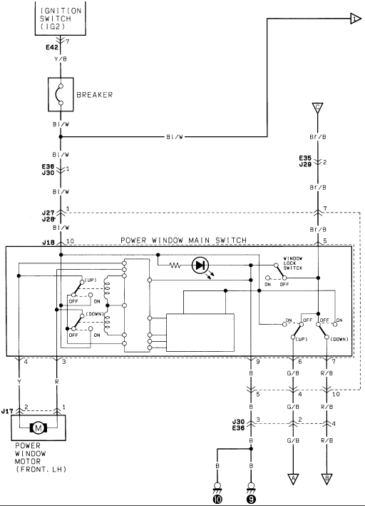
Suzuki Samurai Power Window Wiring Diagram - Main Switch & Motor Circuit
Reference · 1986-1995 SamuraiAll 73 wiring diagrams
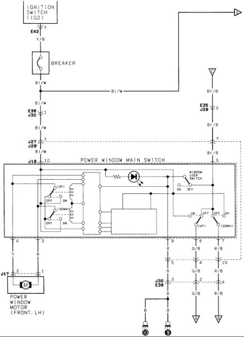
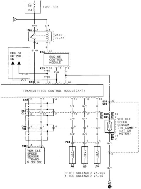
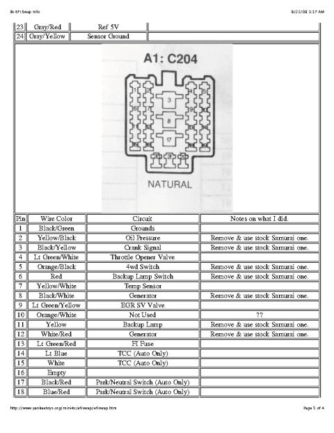
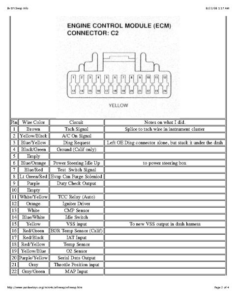
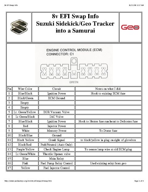

Wiring diagram of the power window circuit showing the main switch, window lock switch, circuit breaker and front LH window motor.
Part of 1986-1995 Suzuki Samurai Wiring Diagrams
This document is a scanned power window wiring diagram, uploaded to a 1986 Suzuki Samurai gallery as part of a larger factory wiring diagram set. It shows the circuit from the ignition switch (IG2 terminal, connector E42, pin 7) through a Y/B wire to a circuit breaker, then via Bl/W wiring through connectors E36/J30 (pin 1) and J27/J28 (pin 1) into the Power Window Main Switch at connector J18 (pin 10). A parallel Br/B feed runs through connector E35/J29 (pin 2) to the switch. The main switch internals are drawn, including UP/DOWN contacts, internal relays, an illumination LED with resistor, a Window Lock Switch (ON/OFF), and secondary UP/DOWN switch positions. Outputs include Y and R wires through connector J17 to the front left power window motor, a B (black) ground path through J30/E36 (pin 3) to two chassis grounds (points 10 and 9), and G/B and R/B wires routed to the right toward other circuits/switches (continuation arrows). Wire colors documented include Y/B, Bl/W, Br/B, Y, R, B, G/B, and R/B. A reader can use this diagram to trace power, ground, and control wiring for the power window system and identify connector pin assignments.
Is this accurate? Sign in to help verify it.
Frequently asked questions
- Where does the power window circuit get its power?
- From the ignition switch IG2 terminal via connector E42 pin 7 on a Y/B wire, through a circuit breaker, then on a Bl/W wire to the power window main switch.
- What wire colors run to the front left power window motor?
- A Y (yellow) wire from pin 4 and an R (red) wire from pin 3 of the power window main switch, passing through connector J17 pins 2 and 1 to the motor.
- How is the power window main switch grounded?
- Through a B (black) wire from pin 9 of the switch, through connector J30/E36 pin 3, splitting to two chassis ground points labeled 10 and 9.
- Does the diagram show a window lock switch?
- Yes, a Window Lock Switch with ON and OFF positions is shown inside the Power Window Main Switch assembly.
- Which connectors are involved in the power window circuit?
- Connectors labeled E42, E36/J30, J27/J28, J18, E35/J29, and J17 are shown in the circuit.






No comments yet.