Home/
Registry/
Suzuki/
Samurai/
1986-1995/
“Little Blue”/
Photo
supermotors.net/registry/media/420710
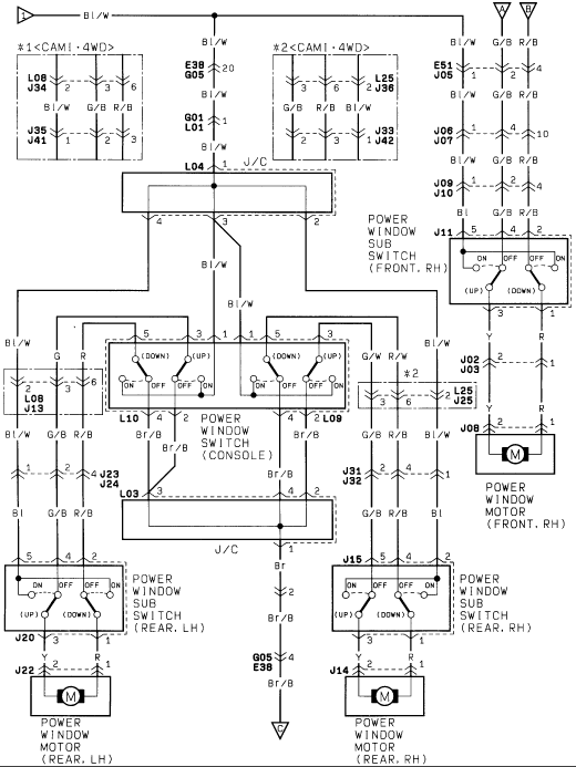
Suzuki Power Window Wiring Diagram - Console Switch, Sub Switches & Motors
Reference · 1986-1995 SamuraiAll 73 wiring diagrams
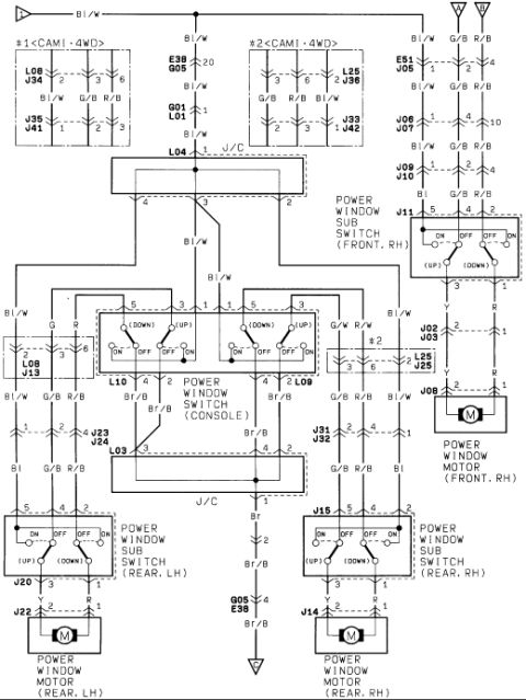
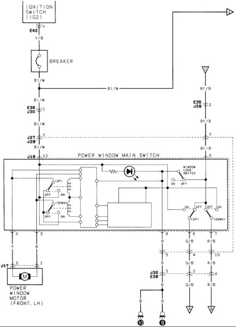
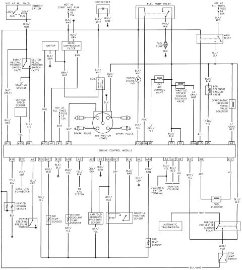
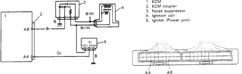

Wiring diagram for power window system showing console and sub-switches, front and rear window motors, and color-coded circuits.
Part of 1986-1995 Suzuki Samurai Wiring Diagrams
This document is a power window system wiring diagram scanned from a factory-style service manual. It shows the complete power window circuit: a master POWER WINDOW SWITCH mounted in the console, three POWER WINDOW SUB SWITCHes (front RH, rear LH, rear RH), and four power window motors (front RH, rear LH, rear RH shown; front LH implied via console switch). The diagram traces wire colors, Bl/W (blue/white) power feed, G/B, R/B, Y, R, G/W, R/W, Br, and Br/B ground, through numbered connectors including E38/G05, G01/L01, L04 and L03 junction connectors (J/C), L08/J34, J35/J41, L25/J36, J33/J42, E51/J05, J06/J07, J09/J10, J11, J02/J03, J08, J23/J24, J31/J32, J15, J20, J22, and J14. Two connector variant blocks are labeled '#1 <CAMI·4WD>' and '#2 <CAMI·4WD>', indicating alternate connector pinouts for CAMI-built 4WD vehicles. Each sub switch shows ON/OFF contact positions for UP and DOWN operation. A reader can use this diagram to trace power window circuits, identify connector pin numbers and wire colors for diagnosing inoperative windows, and locate ground points (Br/B to chassis ground).
Is this accurate? Sign in to help verify it.
Frequently asked questions
- What wire color is the main power feed for the power window circuit?
- The main feed shown running across the top of the diagram and to the console switch is Bl/W (blue/white).
- Which connectors are used for the front right power window motor?
- The front RH power window sub switch is connector J11, feeding through J02/J03 (pins 2 and 1, wires Y and R) to connector J08 at the front RH power window motor.
- What does the <CAMI·4WD> notation mean on this diagram?
- The diagram shows two alternate connector blocks labeled '#1 <CAMI·4WD>' (connectors L08/J34 and J35/J41) and '#2 <CAMI·4WD>' (connectors L25/J36 and J33/J42), indicating different connector pinouts used on CAMI-built 4WD vehicles.
- How are the rear power window motors wired?
- The rear LH motor connects through connector J22 (pins 2 and 1) with Y and R wires from the rear LH sub switch (J20); the rear RH motor connects through J14 (pins 2 and 1) with Y and R wires from the rear RH sub switch (J15).
- Where does the power window circuit ground?
- Ground wires are Br and Br/B, routed through junction connector L03 and connector G05/E38 to a chassis ground symbol at the bottom of the diagram.






No comments yet.