Home/
Registry/
Ford/
Mustang/
1964-1973/
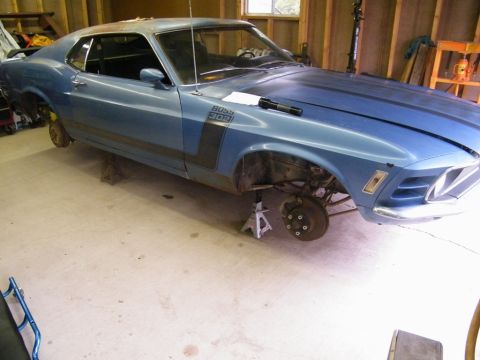
1965 Ford Mustang/
Photo
supermotors.net/registry/media/473073
Homemade Mandrel Tube Bender Plans - DIY Pipe Bending Blueprint & Parts List

Reference · 1964-1973 MustangAll 11 blueprints
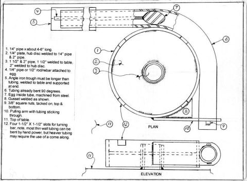
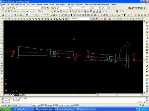
Dimensioned plan-and-elevation drawing of a homemade tubing bender with a numbered fabrication parts list and material notes.
Part of 1964-1973 Ford Mustang Blueprints
This document is a hand-drawn blueprint titled 'Mandrel Bender Plans' showing how to fabricate a homemade mandrel-style tube/pipe bender. It contains two views, a PLAN (top) view showing a large circular bending hub with a curved tube being formed around it, and an ELEVATION (side) view of the table-mounted assembly, with numbered callouts (1-12) keyed to a parts and construction legend. The legend specifies materials and construction steps: a 14" pipe about 4-6" long as the bending drum, a 1/4" plate hub disc welded to the 14" and 2" pipes, a 1-1/2" and 2" pipe pivot arrangement (1-1/2" welded to the table, 2" welded to the hub disc), a 1/4" pipe or 1/2" rod/rebar attached to a steel 'egg' mandrel machined to fit inside the tube being bent, an angle-iron trough longer than the tubing welded to the table, a welded gusset, 3/8" square nuts tacked on top and bottom, a pulling arm with tubing sticking through, and four 1-1/2" x 1-1/2" slots for the turning bar. A note advises that most thin-wall tubing can be bent by hand power, but heavier tubing may require a come-along. This is shop tooling documentation rather than vehicle-specific information.
Is this accurate? Sign in to help verify it.
Frequently asked questions
- What size pipe is used for the bending drum on this homemade mandrel bender?
- A 14" pipe cut to about 4-6" long serves as the bending drum, with a 1/4" plate hub disc welded to the 14" pipe and a 2" pipe.
- How does the bender pivot on the table?
- A 1-1/2" pipe is welded to the table and a 2" pipe is welded to the hub disc, so the 2" pipe rotates over the 1-1/2" pipe as a pivot.
- What is the mandrel and how is it positioned?
- The mandrel is an 'egg' machined from steel that sits inside the tube being bent; it is attached to a 1/4" pipe or 1/2" rod/rebar.
- Can this bender be operated by hand?
- Yes: the plans note that most thin-wall tubing can be bent by hand power, but heavier tubing may require the use of a come-along. Four 1-1/2" x 1-1/2" slots are provided for a turning bar.
- How is the tubing supported during the bend?
- An angle-iron trough, which must be longer than the tubing, is welded to the table and supported at the end; the tubing feeds through it into the pulling arm.


No comments yet.