Home/
Registry/
Ford/
Bronco/
1980-1986/
1984 Ford Bronco/
Photo
supermotors.net/registry/media/475918
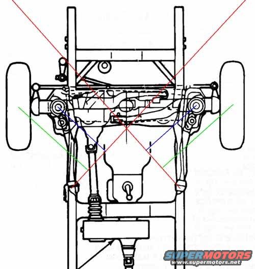
Ford Bronco TTB Front Suspension Symmetry Diagram - Twin Traction Beam Layout
Reference · 1980-1986 BroncoAll 34 schematics





Front axle and suspension schematic viewed from below with diagonal reference lines marking steering and alignment geometry.
Part of 1980-1986 Ford Bronco Schematics
This document is a black-and-white line-art schematic showing a Ford Twin Traction Beam (TTB) style front suspension and frame assembly, viewed from underneath. It depicts the frame rails, crossmember, radius arms, coil spring, steering linkage, differential housing, TTB axle beams with their pivot points, and the front wheels/tires. Overlaid on the factory-style drawing are colored reference lines: a large red 'X' pattern crossing at the center of the axle assembly, along with shorter blue and green diagonal lines drawn from the axle beam pivot and wheel-end areas. Per the filename ('ttbsymetry.jpg'), these lines appear intended to demonstrate the geometric symmetry (or measurement reference points) of the TTB front axle arrangement, useful for checking alignment, frame squareness, or understanding how the two axle beams pivot symmetrically about the vehicle centerline. There is no legend, dimension callouts, part numbers, or readable specifications; a few lines of text along the right margin are cut off and illegible. The drawing itself carries no year, model, or engine applicability statement, so its attribution to a 1984 Ford Bronco comes only from the uploader's claim, though the TTB layout shown is consistent with that vehicle.
Is this accurate? Sign in to help verify it.
Frequently asked questions
- What does this diagram show?
- A bottom-view line drawing of a Twin Traction Beam (TTB) front suspension and frame, with colored reference lines (red X plus blue and green diagonals) overlaid to illustrate the geometric symmetry of the axle beam layout.
- Where do the red reference lines intersect?
- The large red X-pattern lines cross at the center of the axle/differential area of the suspension, on the vehicle centerline.
- Does the diagram include measurements, torque specs, or part numbers?
- No. The drawing contains no legible dimensions, torque values, legends, or part numbers; only a few cut-off, illegible text fragments appear at the right edge.
- What suspension components are visible in the drawing?
- The frame rails, crossmember, TTB axle beams with pivot points, radius arms, a coil spring, steering linkage, differential housing, and the front wheels/tires.
No comments yet.