Home/
Registry/
Ford/
Bronco/
1980-1986/
“DeciBolt (Loud and fast)”/
Photo
supermotors.net/registry/media/48799
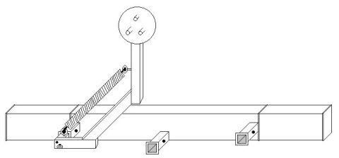
Swing-Away Spare Tire Carrier Schematic Drawing - 1986 Ford Bronco (RJM Design)

Reference · 1980-1986 BroncoAll 34 schematics
Mechanical line-drawing schematic of a fabricated fixture or tool assembly shown mounted on a workbench.
Part of 1980-1986 Ford Bronco Schematics
This document is an untitled, unlabeled line-art schematic (isometric-style drawing) associated with a swing-away spare tire carrier design, uploaded to a 1986 Ford Bronco gallery under the filename 'tire_carrier_rjm_1.jpg'. The drawing depicts a long horizontal rectangular tube, resembling a rear bumper or crossmember, with two small square receiver-style tube stubs projecting from its face. At the left end, a hinged base bracket is shown with a vertical post rising from it. The post is topped by a circular plate containing three keyhole/slot-style openings, presumably for mounting a spare wheel via its lug pattern. A diagonal coil spring runs from partway up the vertical post down to the hinge area at the base, suggesting a spring-assist or return mechanism for swinging the carrier open and closed. The drawing contains no dimensions, part numbers, torque specifications, text labels, or year/model applicability information of any kind, so a reader can learn only the general geometry and concept of the tire carrier mechanism, not fabrication measurements. Nothing in the drawing contradicts the uploader's claim that it relates to a 1986 Ford Bronco.
Is this accurate? Sign in to help verify it.
Frequently asked questions
- What does this schematic show?
- It shows a swing-away spare tire carrier concept: a horizontal rectangular tube (bumper/crossmember) with two square receiver stubs, a hinged base bracket, a vertical post topped by a circular wheel-mount plate with three keyhole slots, and a diagonal coil spring between the post and the hinge base.
- Does the drawing include dimensions or part numbers?
- No. The drawing contains no text at all, no dimensions, part numbers, torque values, or labels.
- How does the spare wheel attach in this design?
- The circular plate at the top of the vertical post has three keyhole-style slots, which appear intended to engage the wheel's lug studs or mounting hardware.
- What is the purpose of the coil spring shown?
- The spring runs diagonally from the vertical post to the hinged base, suggesting it assists or controls the swing motion of the carrier arm.
No comments yet.