Home/
Registry/
Ford/
Bronco/
1987-1991/
“The OJ Special”/
Photo
supermotors.net/registry/media/513969
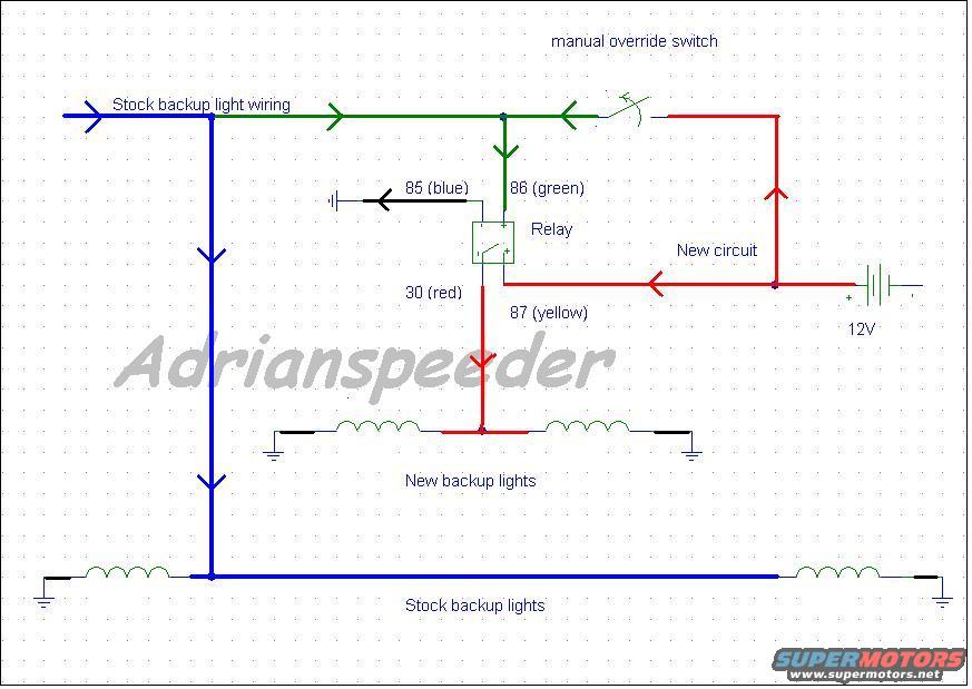
Ford Bronco Auxiliary Backup Lights Relay Wiring Diagram with Override Switch
Reference · 1987-1991 BroncoAll 175 wiring diagrams
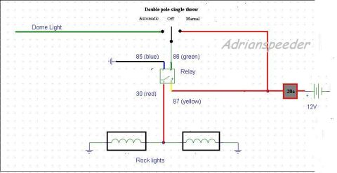
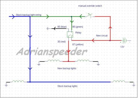
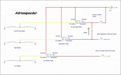
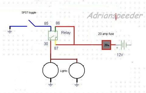
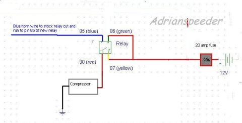
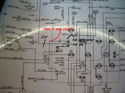
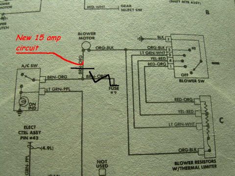
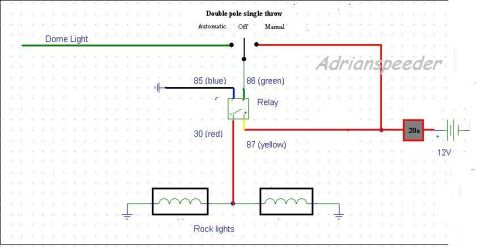





Wiring diagram adding new backup lights via a relay tapped off stock backup wiring with a manual override switch to 12V.
Part of 1987-1991 Ford Bronco Wiring Diagrams
This document is a hand-drawn (CAD-style) wiring diagram showing how to add auxiliary (new) backup lights to a vehicle using a standard 4-pin automotive relay, uploaded to the gallery of a 1988 Ford Bronco. The diagram shows the stock backup light wiring (blue line) feeding the factory backup lights at the bottom. A tap from the stock backup light circuit (green line) feeds relay terminal 86, with terminal 85 (blue) going to ground. A manual override switch is shown in-line on the green trigger circuit so the new lights can be switched on manually, fed from a new 12V circuit (red line). Relay terminal 30 (red) receives power, and terminal 87 (yellow), the diagram labels 30 as the output to the new lights and 87 as connected to the new 12V circuit, powers the pair of new backup lights, each grounded on its own side. Wire colors for the relay terminals are labeled: 85 blue, 86 green, 30 red, 87 yellow. A reader can learn the basic relay hookup for adding high-power auxiliary reverse lights triggered by the factory backup light circuit, with a manual override switch option. The image bears the watermark "Adrianspeeder" and contains no year, model, part numbers, or fuse ratings.
Is this accurate? Sign in to help verify it.
Frequently asked questions
- How are the new backup lights triggered?
- The relay's terminal 86 (green wire) taps into the stock backup light wiring, so when the stock backup lights come on, the relay energizes and powers the new backup lights.
- What are the relay terminal wire colors in this diagram?
- 85 is blue (to ground), 86 is green (trigger from stock backup wiring), 30 is red (to the new backup lights), and 87 is yellow (to the new 12V circuit).
- Can the new backup lights be turned on manually?
- Yes. A manual override switch is shown connecting the new 12V circuit to the relay trigger line, allowing the new lights to be switched on independently of the stock circuit.
- Where does the relay get its power?
- From a new circuit connected to a 12V source (battery), shown in red on the diagram feeding terminal 87 (yellow).
- How is relay terminal 85 wired?
- Terminal 85 (blue) is wired to ground.






No comments yet.