Home/
Registry/
Ford/
Bronco/
1987-1991/
“The OJ Special”/
Photo
supermotors.net/registry/media/508613
Ford Bronco Headlight & Driving Lights Relay Wiring Diagram (Adrianspeeder)

Reference · 1987-1991 BroncoAll 175 wiring diagrams
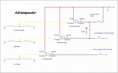
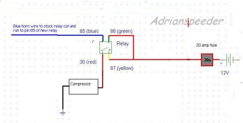
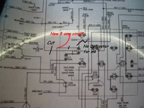
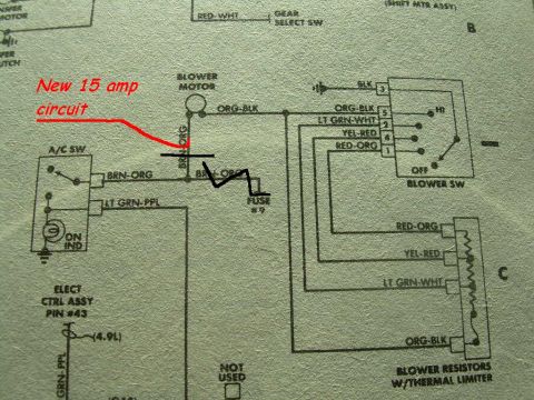
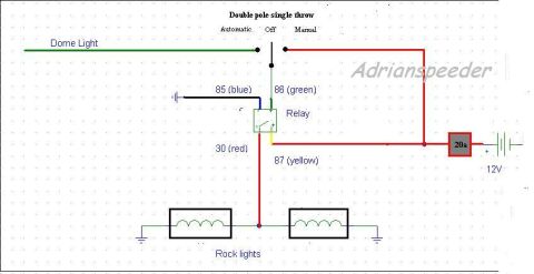

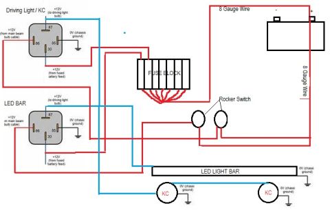








Wiring diagram for driving lights, high beams, and low beams using three relays, a diode, and manual override switch to 12V.
Part of 1987-1991 Ford Bronco Wiring Diagrams
This is a hand-drawn (CAD-style) automotive lighting wiring diagram credited to "Adrianspeeder," uploaded to a 1988 Ford Bronco gallery. It shows how to wire three standard relays, a Driving Lights Relay, a High Beams Relay, and a Low Beams Relay, to control Extra Driving Lights, High Beams, and Low Beams from a 12V battery source. Each relay is drawn with its standard terminals labeled by number and wire color: 30 (red) power input, 85 (blue) coil ground, 86 (green) coil trigger, and 87 (yellow) output to the lamps. Relay terminal 30 on all three relays feeds from a common red 12V power bus. The Driving Lights Relay's trigger (86) is fed through a circuit containing a diode and a "manual override switch," allowing the extra driving lights to be triggered either by the stock high-beam circuit (via the diode) or manually. The High Beams Relay trigger connects to the "Stock Highbeam switch and wiring," and the Low Beams Relay trigger connects to the "Stock Lowbeam switch and wiring," so the factory headlight switch only carries relay coil current while the relays carry lamp current. Each lamp pair is shown grounded to chassis. No part numbers, fuse ratings, or year/model applicability are stated on the document.
Is this accurate? Sign in to help verify it.
Frequently asked questions
- What relay terminals and wire colors does this diagram use?
- Each relay uses terminal 30 (red) for 12V power, 85 (blue), 86 (green) for the trigger from the stock switch wiring, and 87 (yellow) going out to the lights.
- How are the extra driving lights triggered in this diagram?
- The Driving Lights Relay coil is triggered either through a diode from the stock high-beam circuit or through a separate manual override switch, both fed from the 12V source.
- How many relays does this setup use?
- Three relays: a Driving Lights Relay for the extra driving lights, a High Beams Relay, and a Low Beams Relay.
- Where do the relays get their trigger signals for the high and low beams?
- The High Beams Relay trigger (86) connects to the stock high-beam switch and wiring, and the Low Beams Relay trigger connects to the stock low-beam switch and wiring.
- What is the purpose of the diode in the circuit?
- The diode sits between the stock high-beam circuit and the driving lights relay/manual override switch line, isolating the manual override switch so it can power the driving lights without back-feeding the stock high-beam wiring.






No comments yet.