Home/
Registry/
Ford/
Bronco/
1987-1991/
1991 Ford Bronco/
Photo
supermotors.net/registry/media/509453
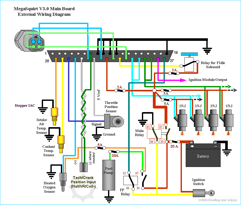
MegaSquirt V3.0 Main Board External Wiring Diagram - Pinout, Relays & Fuses
Reference · 1987-1991 BroncoAll 175 wiring diagrams


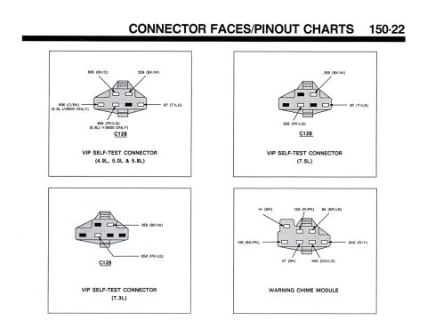
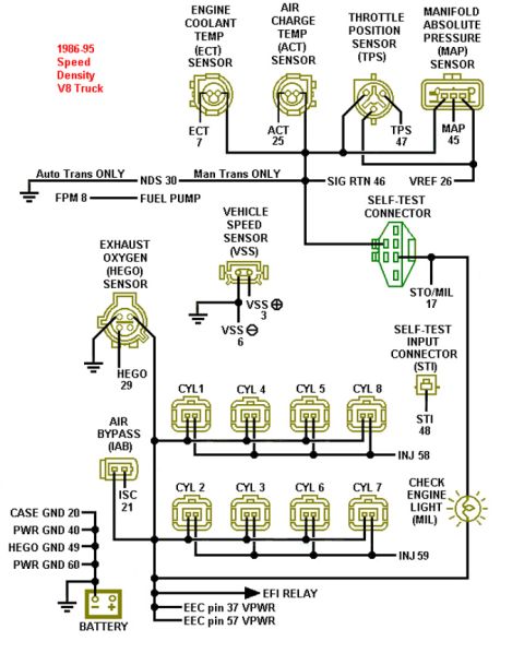
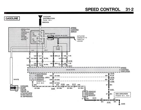
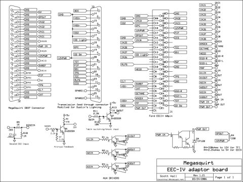




MegaSquirt V3.0 ECU external wiring showing DB37/sensor connector pinout, injectors, fuel pump and idle solenoid relays, CLT/IAT/O2/TPS sensors and fuse ratings.
Part of 1987-1991 Ford Bronco Wiring Diagrams
This document is the external wiring diagram for the MegaSquirt V3.0 Main Board, an aftermarket electronic fuel injection controller by Bowling and Grippo (©2006). It shows the 37-pin main connector (pins 1-19 on the top row, 20-37 on the bottom row) and the color-coded external wiring from the ECU to all supporting components. Depicted circuits include: a Stepper IAC (idle air control), Intake Air Temperature sensor, Coolant Temperature sensor, Heated Oxygen sensor, Throttle Position Sensor (with 5 Vref, Signal, and Ground leads), a Tach/Crank Position input for Hall, VR, or Coil-negative triggering (with + and, leads and a note '(-) where needed'), four fuel injectors (INJ x4), the fuel pump with its FP relay (terminals 30/85/86/87), a Main Relay (30/85/86/87), a relay for a fast-idle (FIdle) solenoid, an Ignition Module/Output line, the battery, and the ignition switch. Inline fuse ratings are marked throughout: 2A for the FIdle relay and ignition-switched feeds, 5A fuses on several sensor/trigger supply lines, 10A for the fuel pump, and 20A on the main battery feed. The diagram is a general MegaSquirt installation reference rather than a factory Ford schematic, useful for anyone converting a vehicle to MegaSquirt EFI.
Is this accurate? Sign in to help verify it.
Frequently asked questions
- What fuse sizes does the MegaSquirt V3.0 external wiring diagram specify?
- The diagram shows 2A fuses for the FIdle solenoid relay and ignition-switched circuits, 5A fuses on several supply lines (including the tach/crank position input), a 10A fuse for the fuel pump circuit, and a 20A fuse on the main relay/battery feed.
- How is the fuel pump wired in the MegaSquirt V3.0 diagram?
- The fuel pump is powered through an FP Relay (terminals 30, 85, 86, 87) with a 10A fuse in its circuit; the relay is controlled by the MegaSquirt board and fed via the ignition switch/battery circuits.
- What sensors connect to the MegaSquirt V3.0 main board?
- The diagram shows the Intake Air Temp. Sensor, Coolant Temp. Sensor, Heated Oxygen Sensor, Throttle Position Sensor (5 Vref, Signal, Ground), and a Tach/Crank Position Input that accepts Hall, VR, or Coil-negative signals.
- How many injectors are shown and how are they powered?
- Four injectors (INJ) are shown, powered through the Main Relay circuit that is fed from the battery via a 20A fuse.
- How many pins does the MegaSquirt V3.0 main connector have?
- The connector is numbered 1 through 19 on the top row and 20 through 37 on the bottom row, i.e., a 37-pin connector.






No comments yet.