Home/
Registry/
Ford/
Bronco/
1987-1991/
1991 Ford Bronco/
Photo
supermotors.net/registry/media/300781
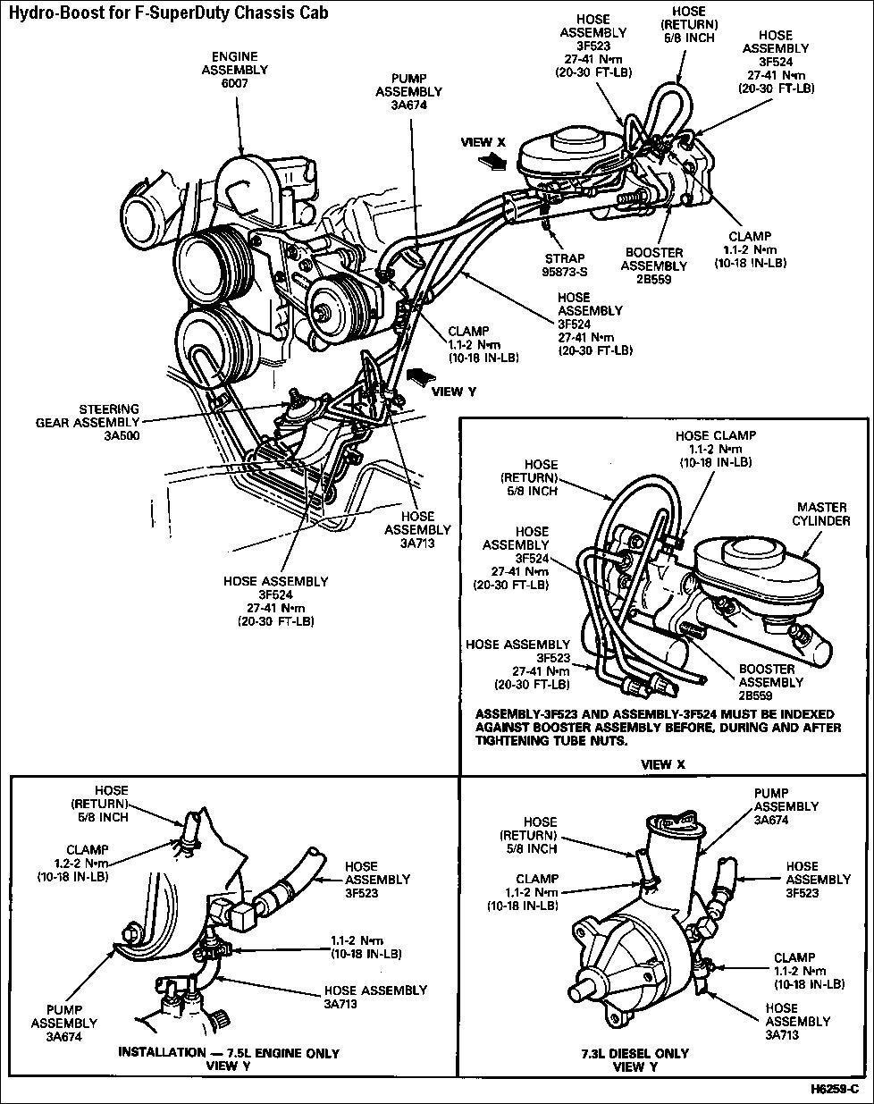
Ford F-Super Duty Chassis Cab Hydro-Boost Diagram - Hose Routing & Torque Specs
Reference · 1987-1991 BroncoAll 61 exploded parts diagrams



Hydro-Boost plumbing/parts diagram for an F-Super Duty chassis cab showing hoses, clamps, pump, booster, and master cylinder with part numbers.
Part of 1987-1991 Ford Bronco Exploded Parts Diagrams
This is a Ford service-manual exploded parts diagram titled "Hydro-Boost for F-SuperDuty Chassis Cab," showing the hydraulic (Hydro-Boost) power brake booster system and its hose routing. The main illustration shows the engine assembly (6007), power steering pump assembly (3A674), steering gear assembly (3A500), booster assembly (2B559), and the pressure and return hose assemblies (3F523, 3F524, 3A713) with their routing between the pump, steering gear, and booster. Torque specifications are given for the hose tube nuts (27-41 N•m / 20-30 ft-lb) and hose clamps (1.1-2 N•m / 10-18 in-lb). A 5/8-inch return hose and retaining strap (95873-S) are also called out. Inset VIEW X details the booster and master cylinder area, with a note that hose assemblies 3F523 and 3F524 must be indexed against the booster assembly before, during, and after tightening the tube nuts. Two VIEW Y insets show pump-end hose connections specific to the 7.5L gasoline engine and the 7.3L diesel engine. The figure reference is H6259-C. A reader can learn the part numbers, hose routing, and fastener torque values for installing or servicing the Hydro-Boost system on F-Super Duty chassis cab trucks.
Is this accurate? Sign in to help verify it.
Frequently asked questions
- What is the torque spec for the Hydro-Boost hose assembly tube nuts?
- Hose assemblies 3F523 and 3F524 are torqued to 27-41 N•m (20-30 ft-lb).
- What torque is specified for the hose clamps?
- The hose clamps are tightened to 1.1-2 N•m (10-18 in-lb); one callout shows 1.2-2 N•m (10-18 in-lb).
- What size is the Hydro-Boost return hose?
- The return hose is 5/8 inch.
- Is there a special note for installing hose assemblies 3F523 and 3F524?
- Yes: the diagram states that Assembly-3F523 and Assembly-3F524 must be indexed against the booster assembly before, during, and after tightening the tube nuts.
- Does the diagram differ between engines?
- Yes, it includes separate VIEW Y pump-end installation views for the 7.5L engine and the 7.3L diesel engine.
- What is the part number for the Hydro-Boost booster assembly?
- The booster assembly is part number 2B559; the pump assembly is 3A674 and the steering gear assembly is 3A500.






No comments yet.