Home/
Registry/
Ford/
Bronco/
1987-1991/
1991 Ford Bronco/
Photo
supermotors.net/registry/media/438353
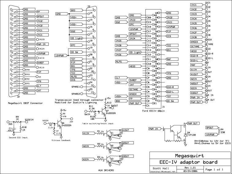
MegaSquirt EEC-IV Adaptor Board Schematic - Ford 60-Pin Piggyback Wiring
Reference · 1987-1991 BroncoAll 110 schematics






Electronic schematic of a MegaSquirt EEC-IV adapter board, page 1, showing DB37 and Ford 60-pin connector pinouts and circuit components.
Part of 1987-1991 Ford Bronco Schematics
This document is an electronic schematic for a "Megasquirt EEC-IV adaptor board," Rev 1.21, drawn by Scott Hall and dated 03/24/2006 (contact [email protected]), Page 1 of 1. It shows how a MegaSquirt engine management system connects to a Ford EEC-IV 60-pin ECU connector via a piggyback adaptor board. The drawing details three main connectors: the MegaSquirt DB37 connector with signals such as FP, SPOUT, INJ1/INJ2, IAC1A/IAC2B, PWM IN, 12VPWR, SVREF, PIP, TPS, CLT, IAT and spare pins; a transmission feed-through connector (noted as "Modified for Dustin's Lightning") carrying E4OD-type signals like BOO, VSS+/-, SS1, SS2, EPC, TCC, MLPS, CCS, OD light, OD SW, TOT; and the Ford EEC-IV 60-pin connector (J1) mapping injector outputs INJ1-INJ8, HEGO/EGO-R/EGO-L, MAF, KNOCK, OCTANE and other signals. Support circuitry includes a Second EGO Input (R9 1K, R10 1M, C1.22uF), a Nitrous Feedback circuit with a 2n2222A transistor, a table switching/knock input circuit, three auxiliary drivers using ZTX450 transistors, and a TIP120-based PWM/SPOUT driver with a note that R4=330 ohms to 12V for TFI ignition or 2.2k ohms to 5V for EDIS. Useful for anyone wiring MegaSquirt to a Ford EEC-IV harness.
Is this accurate? Sign in to help verify it.
Frequently asked questions
- What is this schematic for?
- It is the wiring schematic for a MegaSquirt EEC-IV adaptor board (Rev 1.21 by Scott Hall, dated 03/24/2006), which connects a MegaSquirt ECU via a DB37 connector to the Ford EEC-IV 60-pin connector, including a transmission feed-through connector.
- What value should R4 be for TFI vs EDIS ignition?
- The schematic notes R4=330 ohms to 12V for TFI and R4=2.2k ohms to 5V for EDIS on the TIP120 PWM/SPOUT driver circuit.
- What transistors are used in the auxiliary driver circuits?
- The three AUX DRIVERS (A1, A2, A3) each use a ZTX450 transistor (Q1, Q2, Q3) with a 1k base resistor and a diode, driving A1OUT, A2OUT, and A3OUT.
- What transmission signals pass through the adaptor board?
- The transmission feed-through connector carries BOO, VSS+, VSS-, SS1, SS2, OD light, EPC, OD SW, TOT, PIP, TPS, TCC, MLPS, CCS, plus SPARE1 and SPARE2.
- How is the second oxygen sensor input wired?
- The "Second EGO Input" circuit runs EGO2IN through R9 (1K) with a .22uF capacitor (C1) and R10 (1M) to ground.






No comments yet.