Home/
Registry/
Ford/
Crown Victoria/
1998-2011/
“None Yet”/
Photo
supermotors.net/registry/media/520253
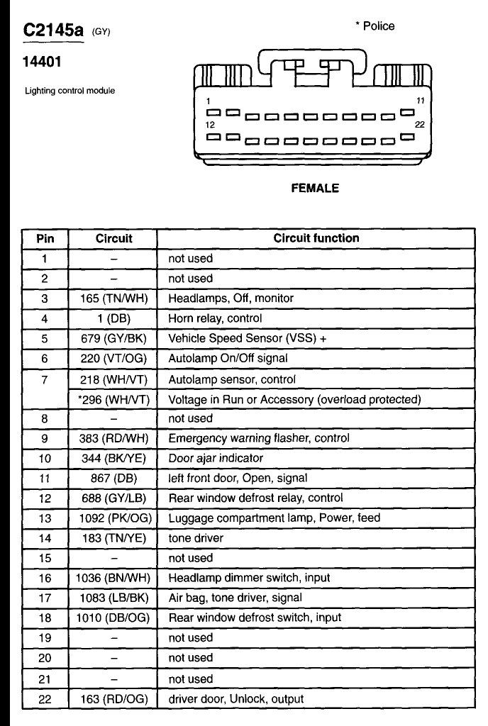
Ford Crown Victoria Lighting Control Module Connector C2145a Pinout (22-Pin)
Reference · 1998-2011 Crown VictoriaAll 29 wiring diagrams
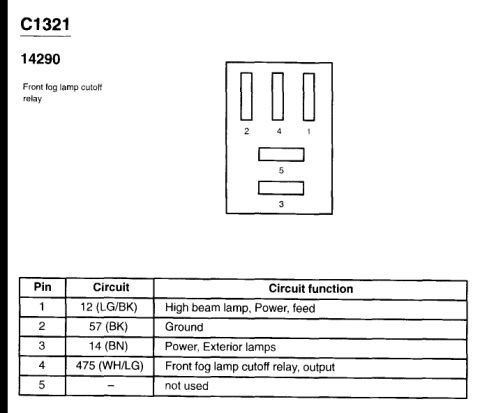
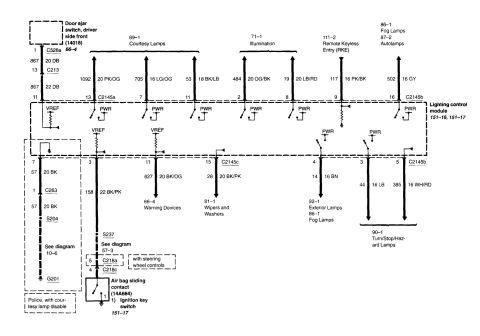
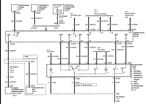
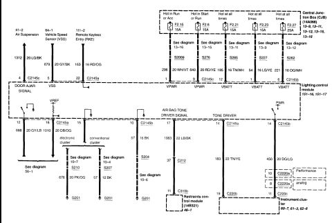
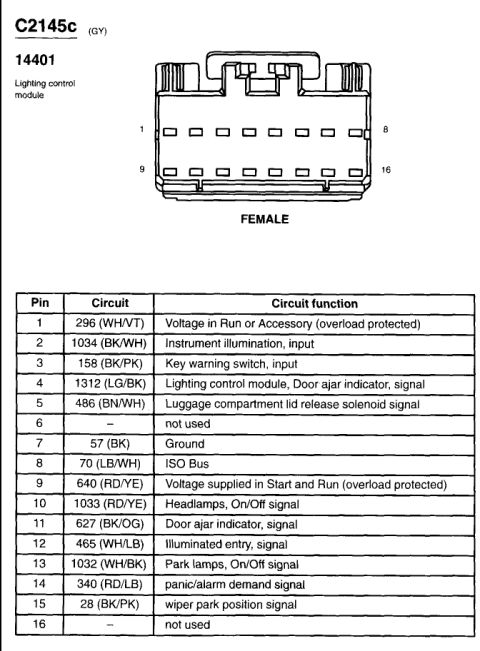
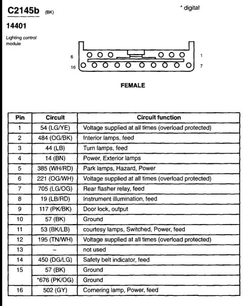
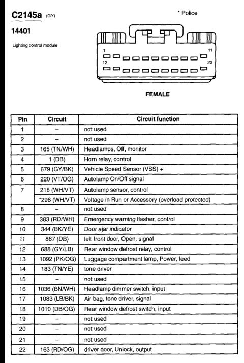
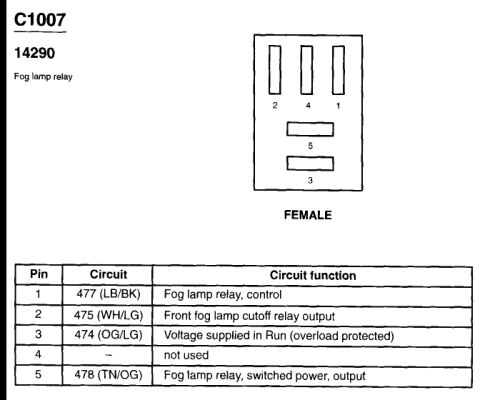
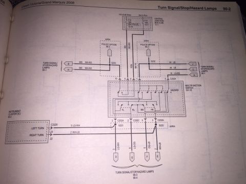
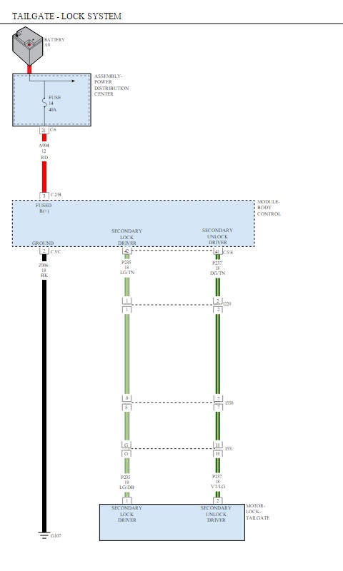

Connector C2145a (GY), lighting control module 14401, 22-pin female pinout mapping each pin to its circuit and function: headlamps, horn relay, VSS, autolamp sensor, defrost relay, air bag tone driver, door unlock output.
Part of 1998-2011 Ford Crown Victoria Wiring Diagrams
This document is a connector pinout reference for Ford connector C2145a (gray, harness/part reference 14401), which connects to the Lighting Control Module (LCM). It shows a 22-pin female connector illustration with pins 1-11 across the top row and 12-22 across the bottom row, followed by a table listing each pin's circuit number, wire color code, and circuit function. Key circuits include: pin 3 circuit 165 (TN/WH) headlamps off monitor; pin 4 circuit 1 (DB) horn relay control; pin 5 circuit 679 (GY/BK) Vehicle Speed Sensor (VSS) +; pins 6-7 autolamp on/off signal and sensor control (with an asterisked Police-variant circuit 296 WH/VT for voltage in Run or Accessory, overload protected); pin 9 circuit 383 (RD/WH) emergency warning flasher control; pin 10 door ajar indicator; pin 11 left front door open signal; pins 12 and 18 rear window defrost relay control and switch input; pin 13 luggage compartment lamp power feed; pin 14 tone driver; pin 16 headlamp dimmer switch input; pin 17 air bag tone driver signal; and pin 22 circuit 163 (RD/OG) driver door unlock output. Pins 1, 2, 8, 15, 19, 20, and 21 are not used. Useful for diagnosing LCM-related lighting, chime, and door lock issues.
Is this accurate? Sign in to help verify it.
Frequently asked questions
- What connector is shown in this diagram?
- Connector C2145a, a gray (GY) 22-pin female connector for the Lighting Control Module (reference 14401), with pins 1-11 on the top row and 12-22 on the bottom row.
- Which pin carries the Vehicle Speed Sensor signal at the lighting control module?
- Pin 5, circuit 679 with a gray/black (GY/BK) wire, is the Vehicle Speed Sensor (VSS) + input.
- Which pins on C2145a are not used?
- Pins 1, 2, 8, 15, 19, 20, and 21 are listed as not used.
- What does the asterisk (*) on circuit 296 mean?
- The asterisk denotes the Police variant. On pin 7, Police vehicles use circuit 296 (WH/VT), 'Voltage in Run or Accessory (overload protected)', instead of/alongside circuit 218 (WH/VT) autolamp sensor control.
- Which pin controls the rear window defrost relay?
- Pin 12, circuit 688 with a gray/light blue (GY/LB) wire, is the rear window defrost relay control; pin 18, circuit 1010 (DB/OG), is the defrost switch input.

No comments yet.