Home/
Registry/
Ford/
Crown Victoria/
1998-2011/
“None Yet”/
Photo
supermotors.net/registry/media/520257
2004 Ford Crown Victoria Wiring Diagram - Lighting Control Module & Headlight Switch

Reference · 1998-2011 Crown VictoriaAll 29 wiring diagrams
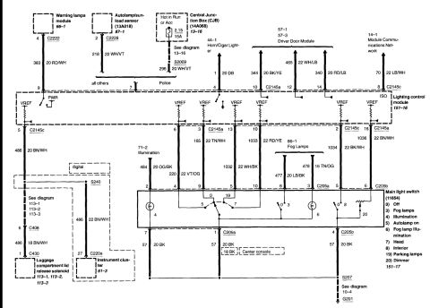
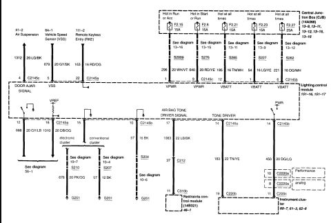
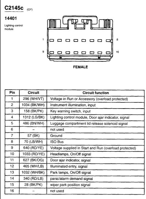
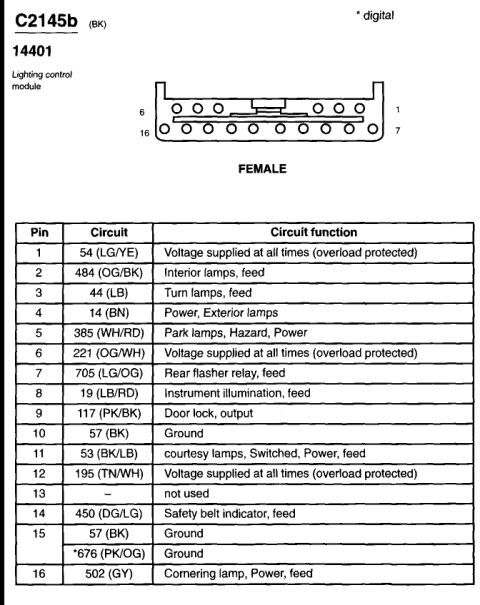
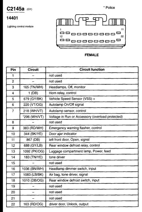
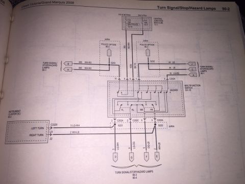
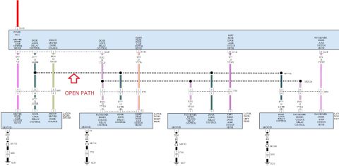
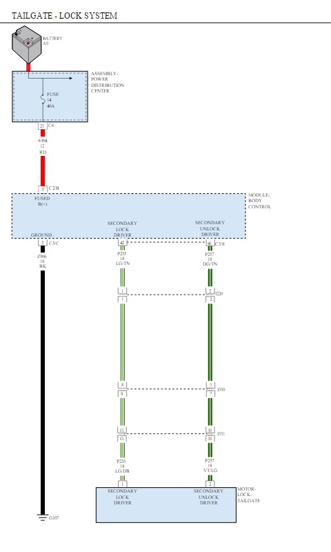
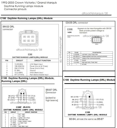

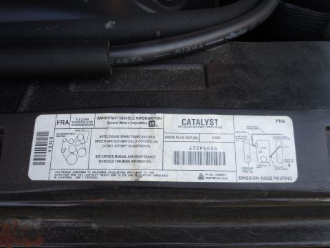
Electrical wiring diagram of lighting and fog lamp circuits with color-coded wires, connectors, and the main light switch.
Part of 1998-2011 Ford Crown Victoria Wiring Diagrams
This scanned wiring diagram page documents the exterior lighting control circuits centered on the Lighting Control Module (diagram cell 151-16) and the Main Light Switch (part designation 11654, cell 151-17). Inputs to the lighting control module include the Warning Lamps Module (circuit 383, 20 RD/WH), the Autolamp/Sun-Load Sensor (13A018, circuit 218, 22 WH/VT, with 'all others' vs. 'Police' variants), a Hot-in-Run-or-Acc feed through Central Junction Box (14A068) fuse 2.15 (15A) via splice S2009 (circuit 296, 20 WH/VT), the Horn/Cigar Lighter (circuit 1, 20 DB), the Driver Door Module (circuits 344 20 BK/YE, 465 22 WH/LB, 340 20 RD/LB), and the Module Communications Network ISO line (circuit 70, 22 LB/WH). Outputs run through connectors C2145a/C2145c to the main light switch (connectors C205a and C205b), whose legend lists positions: Off, Fog lamps, Illumination, Autolamp on, Fog lamp illumination, Head, Interior, Parking lamps, and Dimmer. Additional branches feed the fog lamps (circuits 477, 478), illumination (circuits 484, 220, 1032), the instrument cluster (circuit 486, connector C220a pin 27), and the luggage compartment lid release solenoid (C408/C430). Grounds converge at splice S207 to ground G201 (circuits 57, 20 BK).
Is this accurate? Sign in to help verify it.
Frequently asked questions
- What fuse powers the lighting control module's hot-in-run/acc feed?
- Fuse 2.15, a 15A fuse in the Central Junction Box (CJB, 14A068), feeding circuit 296 (20 WH/VT) through splice S2009.
- What are the positions of the main light switch (11654)?
- 0) Off, 3) Fog lamps, 4) Illumination, 5) Autolamp on, 6) Fog lamp illumination, 7) Head, 8) Interior, 19) Parking lamps, 20) Dimmer.
- What wire colors connect the driver door module to the lighting control module?
- Circuit 344 (20 BK/YE) to pin 10, circuit 465 (22 WH/LB) to pin 12, and circuit 340 (20 RD/LB) to pin 14 of connector C2145a.
- How are the fog lamps wired from the main light switch?
- Circuit 477 (20 LB/BK) on pin 6 and circuit 478 (16 TN/OG) on pin 3 of connector C205a lead to the fog lamps (diagram cell 86-1).
- Where does the main light switch ground?
- Ground circuits 57 (20 BK) from pins 7, 1 (C205a), and 4 (C205b) join at splice S207 and go to ground G201; see diagram 10-4.

No comments yet.