Home/
Registry/
Ford/
Crown Victoria/
1998-2011/
“None Yet”/
Photo
supermotors.net/registry/media/520261
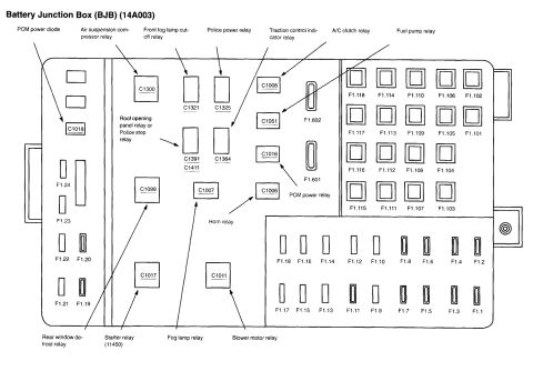
Ford C1007 Fog Lamp Relay Connector Pinout - 14290 Wire Colors & Circuits

Reference · 1998-2011 Crown VictoriaAll 29 wiring diagrams
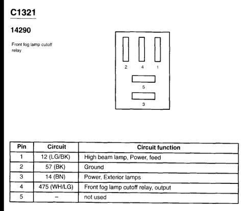
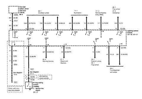
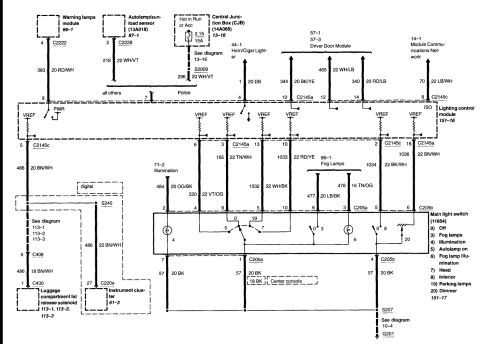
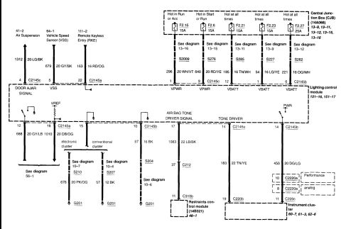
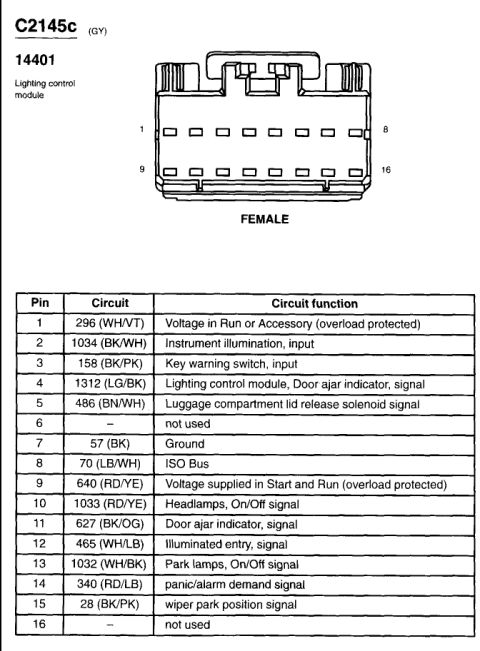
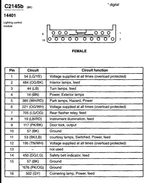
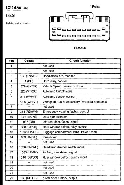
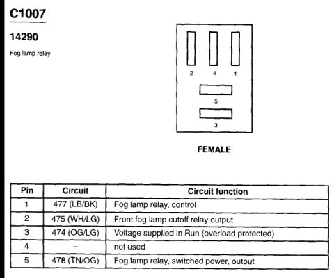
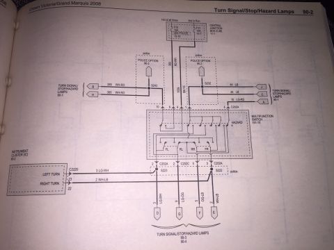
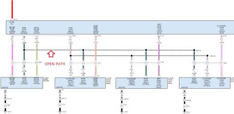
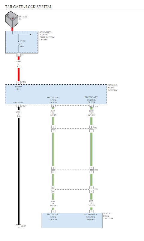
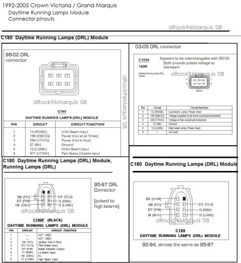


Connector pinout diagram for the fog lamp relay listing pin numbers, wire colors, and circuit functions.
Part of 1998-2011 Ford Crown Victoria Wiring Diagrams
This document is a connector pinout reference for Ford connector C1007, associated with part/base number 14290, identified as the fog lamp relay connector. It includes a face-view illustration of the FEMALE connector showing the physical arrangement of its five cavities: pins 2, 4, and 1 are vertical slots in the top row, pin 5 is a horizontal slot in the middle, and pin 3 is a horizontal slot at the bottom. Below the illustration, a table lists each pin, its circuit number and wire color code, and its circuit function: Pin 1 carries circuit 477 (Light Blue/Black) for fog lamp relay control; Pin 2 carries circuit 475 (White/Light Green) for the front fog lamp cutoff relay output; Pin 3 carries circuit 474 (Orange/Light Green), which is voltage supplied in Run (overload protected); Pin 4 is not used; and Pin 5 carries circuit 478 (Tan/Orange) for the fog lamp relay switched power output. A reader can use this document to identify wires at the fog lamp relay socket for diagnostics, testing relay control and output circuits, or repairing fog lamp wiring. The scan was uploaded to a 2004 Ford Crown Victoria gallery, though the document itself does not state a year or model.
Is this accurate? Sign in to help verify it.
Frequently asked questions
- What is connector C1007 on a Ford?
- According to the document, C1007 (14290) is the fog lamp relay connector, shown as a female connector with five cavities.
- What wire controls the fog lamp relay at C1007?
- Pin 1, circuit 477 (LB/BK: Light Blue/Black), is the fog lamp relay control wire.
- Which pin on the fog lamp relay connector provides switched power output?
- Pin 5, circuit 478 (TN/OG: Tan/Orange), is the fog lamp relay switched power output.
- Which pin at C1007 receives voltage in Run?
- Pin 3, circuit 474 (OG/LG: Orange/Light Green), carries voltage supplied in Run and is overload protected.
- Are all five pins on connector C1007 used?
- No. Pin 4 is listed as 'not used'; pins 1, 2, 3, and 5 have assigned circuits.



No comments yet.