Home/
Registry/
Ford/
Crown Victoria/
1998-2011/
“None Yet”/
Photo
supermotors.net/registry/media/520256
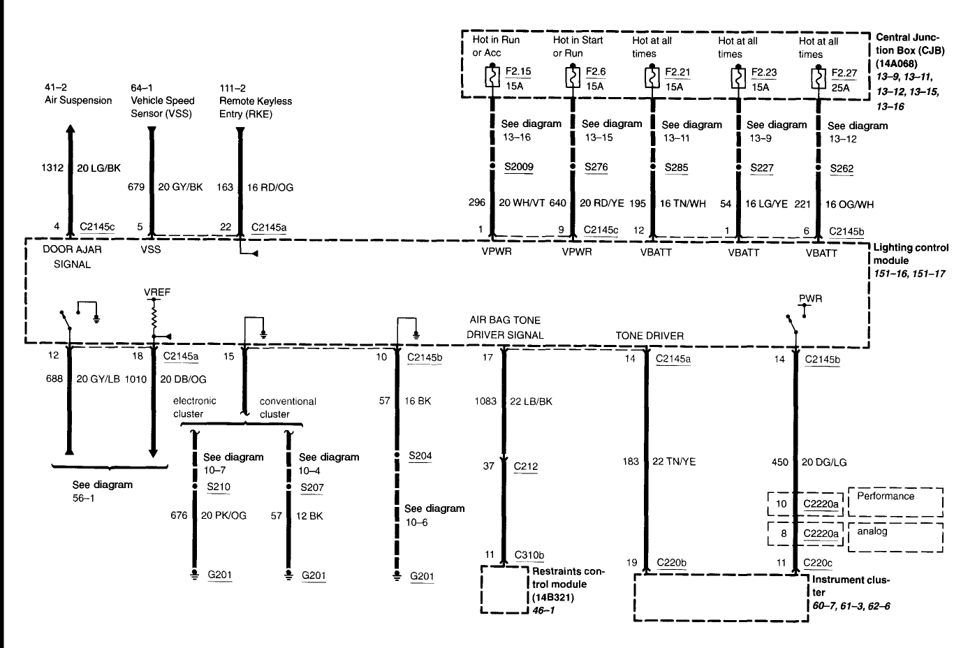
2004 Ford Crown Victoria Lighting Control Module Wiring Diagram - LCM Power/Fuses
Reference · 1998-2011 Crown VictoriaAll 29 wiring diagrams
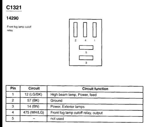
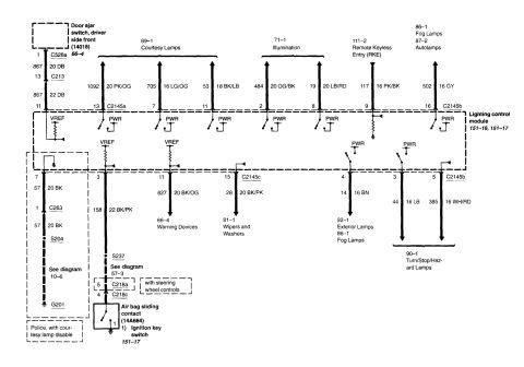
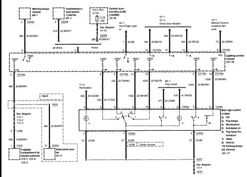
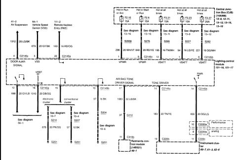
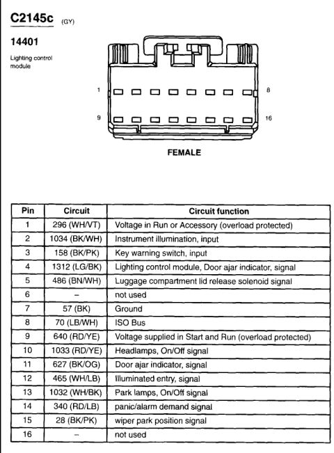
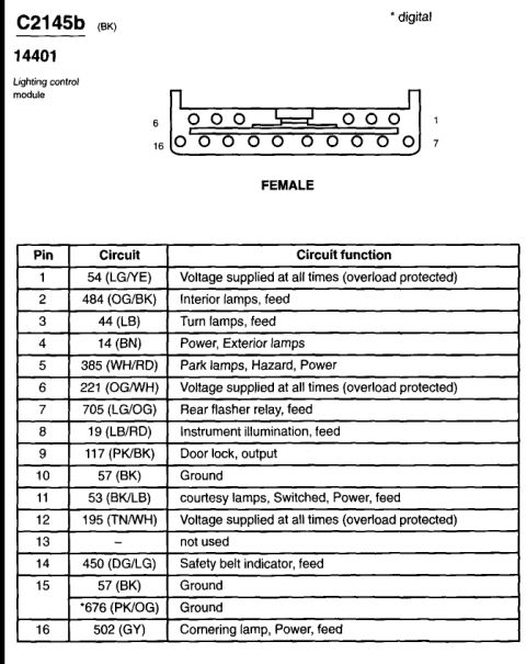
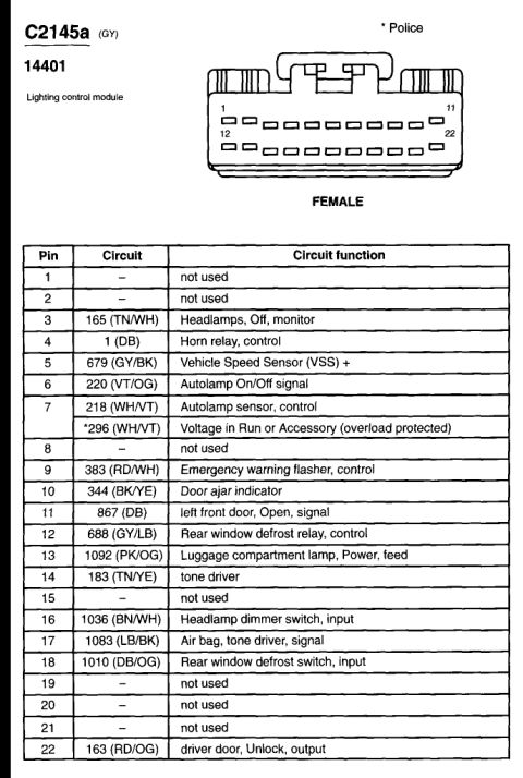

Electrical wiring diagram showing fuses, color-coded circuits, connectors, and module connections.
Part of 1998-2011 Ford Crown Victoria Wiring Diagrams
This is a Ford factory-style wiring diagram page centered on the Lighting Control Module (LCM), referenced to diagram cells 151-16 and 151-17. The top of the page shows the Central Junction Box (CJB, part designation 14A068) with five fuses feeding the module: F2.15 (15A, Hot in Run or Acc), F2.6 (15A, Hot in Start or Run), F2.21 (15A, Hot at all times), F2.23 (15A, Hot at all times), and F2.27 (25A, Hot at all times). Each feed lists its circuit number, wire gauge/color (e.g., 296 20 WH/VT, 640 20 RD/YE, 195 16 TN/WH, 54 16 LG/YE, 221 16 OG/WH), splice (S2009, S276, S285, S227, S262), and module pin/connector (C2145a/b/c) for VPWR and VBATT inputs. Input signals include Air Suspension (Door Ajar Signal, 1312 20 LG/BK), Vehicle Speed Sensor (679 20 GY/BK), and Remote Keyless Entry (163 16 RD/OG). Outputs include grounds to G201 (with separate paths for electronic vs. conventional clusters via splices S210/S207), an Air Bag Tone Driver Signal (1083 22 LB/BK) to the Restraints Control Module (14B321), a Tone Driver circuit (183 22 TN/YE) to the instrument cluster, and a PWR feed (450 20 DG/LG) to the instrument cluster with Performance/analog cluster connector options (C2220a).
Is this accurate? Sign in to help verify it.
Frequently asked questions
- Which fuses power the Lighting Control Module (LCM)?
- Five Central Junction Box fuses feed the module: F2.15 (15A, Hot in Run or Acc), F2.6 (15A, Hot in Start or Run), F2.21 (15A, Hot at all times), F2.23 (15A, Hot at all times), and F2.27 (25A, Hot at all times).
- What wire color and circuit is the VSS input to the Lighting Control Module?
- The Vehicle Speed Sensor input is circuit 679, a 20-gauge GY/BK wire, entering the module at pin 5.
- Where does the Air Bag Tone Driver Signal from the LCM go?
- It leaves module pin 17 on circuit 1083 (22 LB/BK), passes through connector C212 pin 37, and reaches the Restraints Control Module (14B321) at pin 11 of connector C310b.
- What are the LCM ground circuits shown?
- Grounds go to G201: for the electronic cluster via splice S210 on circuit 676 (20 PK/OG), for the conventional cluster via splice S207 on circuit 57 (12 BK), and also via pin 10 (C2145b) on circuit 57 (16 BK) through splice S204.
- What circuit feeds power from the LCM to the instrument cluster?
- Circuit 450, a 20-gauge DG/LG wire from pin 14 (C2145b), routes to the instrument cluster through connector C2220a (pin 10 for Performance, pin 8 for analog cluster) and pin 11 of C220c.

No comments yet.