Home/
Registry/
Ford/
Crown Victoria/
1998-2011/
“None Yet”/
Photo
supermotors.net/registry/media/520259
2004 Ford Crown Victoria Lighting Control Module Wiring Diagram - Circuits & Pins

Reference · 1998-2011 Crown VictoriaAll 29 wiring diagrams
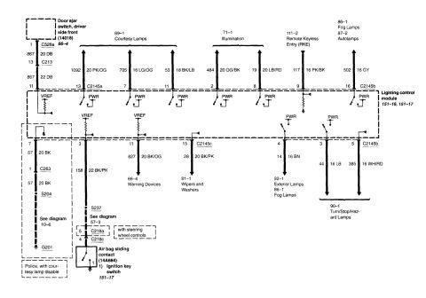
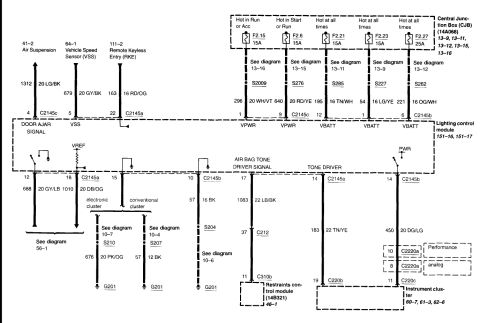
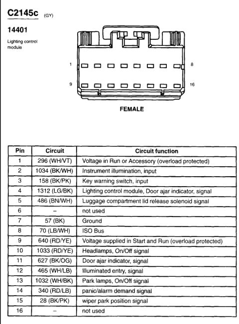
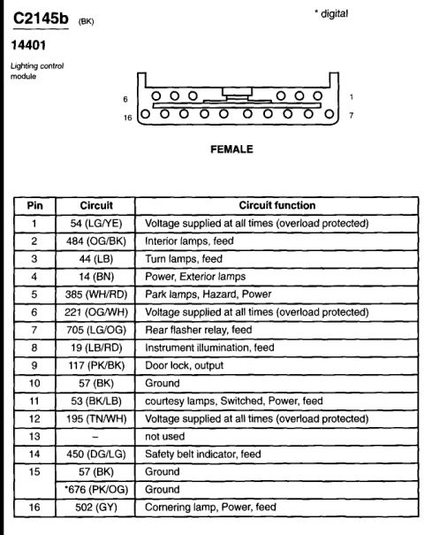
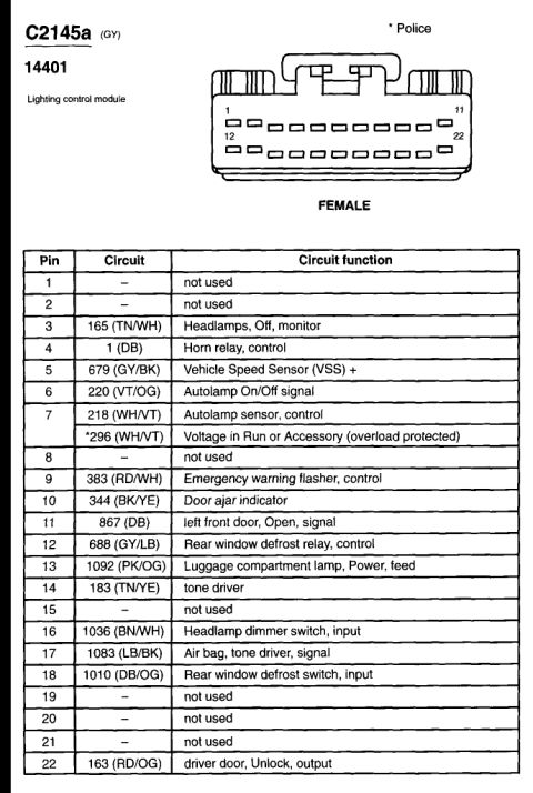
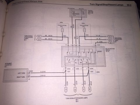
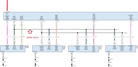
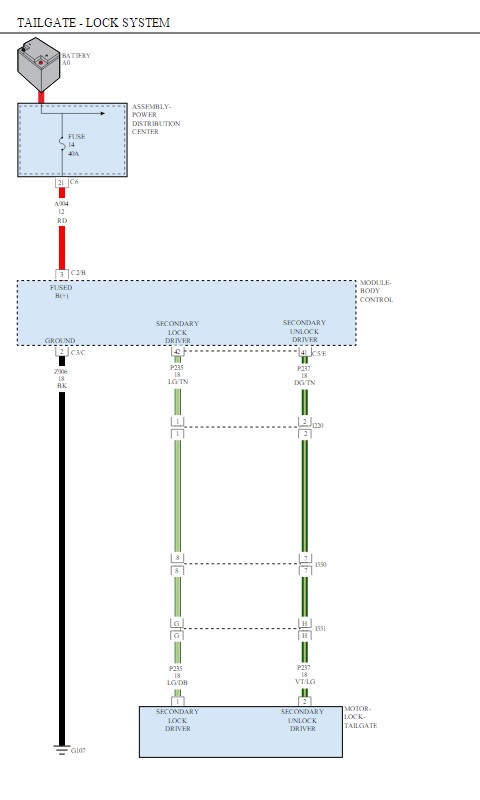
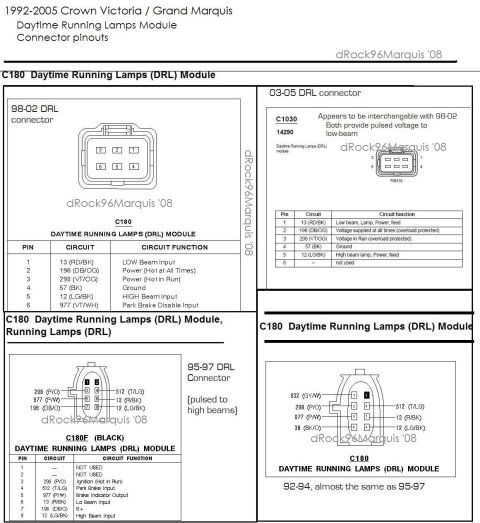

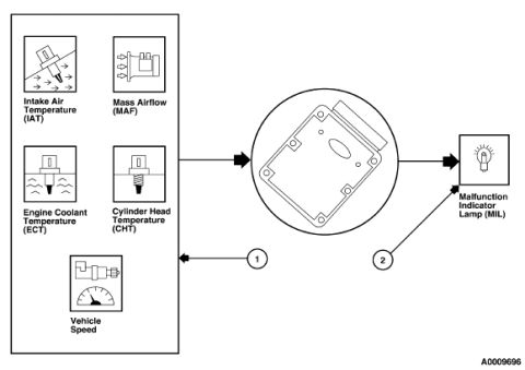
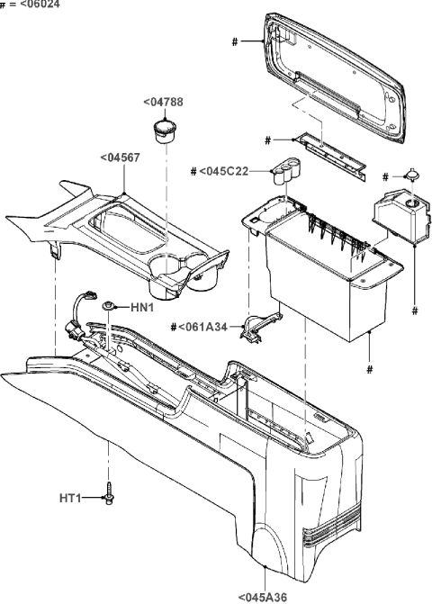
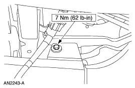
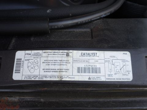
Electrical wiring diagram showing lighting control module circuits for courtesy, fog, and turn/stop lamps.
Part of 1998-2011 Ford Crown Victoria Wiring Diagrams
This document is one page of a Ford factory-style wiring diagram showing circuits connected to the Lighting Control Module (LCM), referenced to diagram sections 151-16 and 151-17. Across the top, inputs and related circuits are shown: the driver-side front door ajar switch (part 14018, connectors C526a and C213, circuit 867, dark blue wire), courtesy lamps (diagram 89-1; circuits 1092 20 PK/OG, 705 16 LG/OG, 53 18 BK/LB via connector C2145a), illumination (71-1; circuits 484 20 OG/BK and 19 20 LB/RD), remote keyless entry (111-2; circuit 117 16 PK/BK), and fog lamps/autolamps (86-1, 87-2; circuit 502 16 GY via C2145b). Below the module, outputs include ground circuit 57 (20 BK) through connector C263, splice S204 and ground G201; circuit 158 (22 BK/PK) through splice S237, connectors C218a/C218c to the air bag sliding contact (14A664) and ignition key switch; circuit 627 (20 BK/OG) to warning devices (66-4); circuit 28 (20 BK/PK) to wipers and washers (81-1); circuit 14 (16 BN) to exterior/fog lamps (92-1, 86-1); and circuits 44 (16 LB) and 385 (16 WH/RD) to turn/stop/hazard lamps (90-1). Notes reference a police option with courtesy lamp disable and a steering-wheel-controls variant. Readers can identify wire gauges, colors, circuit numbers, connector pins, and cross-referenced diagram pages.
Is this accurate? Sign in to help verify it.
Frequently asked questions
- What circuit and wire feed the courtesy lamps from the lighting control module?
- The courtesy lamps (diagram 89-1) connect through circuits 1092 (20 PK/OG, pin 13 of C2145a), 705 (16 LG/OG, pin 7), and 53 (18 BK/LB, pin 11).
- What wire goes from the LCM to the driver's front door ajar switch?
- Circuit 867, a 20-gauge dark blue (DB) wire through connector C526a pin 1 and connector C213 pin 13 (changing to 22 DB), entering the LCM at pin 11. The switch part number is 14018.
- Where does the lighting control module ground?
- Through pin 7 on circuit 57 (20 BK), connector C263, splice S204, and ground G201 (see diagram 10-6). A note indicates a 'Police, with courtesy lamp disable' variant on this branch.
- Which circuits feed the turn/stop/hazard lamps?
- Circuit 44 (16 LB) from pin 3 and circuit 385 (16 WH/RD) from pin 5 of connector C2145b go to the turn/stop/hazard lamps (diagram 90-1).
- What connects to the air bag sliding contact in this diagram?
- Circuit 158 (22 BK/PK) from LCM pin 3 runs through splice S237, connectors C218a (pin 5) and C218c (pin 4) to the air bag sliding contact (14A664), noted with the ignition key switch (151-17) and a 'with steering wheel controls' variant.

No comments yet.