1981-1983 Ford Bronco/F-Series Wiring Diagram - Instrument Panel & Underdash
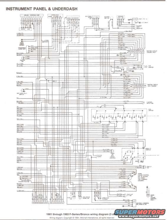
Instrument panel and underdash wiring diagram for 1981-83 Ford F-Series and Bronco with color-coded circuits.
This document is page 3 of a 4-part wiring diagram set covering 1981 through 1983 Ford F-Series and Bronco trucks, published by Mitchell International (copyright 1994). It depicts the Instrument Panel and Underdash wiring. Components shown include the cruise control amplifier and servo unit, windshield wiper/washer switch, wiper governor, windshield wiper motor, air conditioning mode switch, blower motor, blower motor switch and resistor, speed cable sensor, clutch switch, printed circuit connectors (separate versions for gauge and non-gauge clusters), cigar lighter, glove box light and switch, clock, differential lock-out switch, 4-wheel drive indicator, ignition switch, headlight switch, dome light feed, fog light switch, hazard flasher, direction (turn signal) flasher, stop light switch, low brake warning switch, back-up light switch, horn switch (cruise control only), heated rear window switch/timer/indicator, and the combined horn/cruise/directional/hazard switch connector on the steering column. Wire color abbreviations (e.g., LT GRN-PPL, DK GRN-YEL, WHT-RED, BLK-LT GRN) are labeled throughout, along with tach-only and A/C-only circuit notations. A reader can trace instrument panel and underdash circuits and identify wire colors for these systems on 1981-1983 trucks.
Is this accurate? Sign in to help verify it.
Frequently asked questions
- What vehicles does this wiring diagram cover?
- The caption states it applies to 1981 through 1983 Ford F-Series and Bronco trucks; this is sheet 3 of 4.
- What systems are shown on this page of the diagram?
- The instrument panel and underdash wiring, including cruise control amp and servo, wiper/washer switch and motor, blower motor and resistor, ignition switch, headlight switch, hazard and direction flashers, stop light switch, printed circuit connectors, cigar lighter, glove box light, clock, fog light switch, back-up light switch, and heated rear window switch/timer.
- Does the diagram distinguish between gauge and non-gauge instrument clusters?
- Yes. It shows two printed circuit connectors: one labeled 'PRINTED CIRCUIT (GAUGE ONLY)' and another labeled 'PRINTED CIRCUIT (EXC GAUGE)', each with numbered pins.
- Are tachometer-specific wires identified?
- Yes. Wires marked '(TACH ONLY)' include a DK GRN-YEL wire and a BLK-LT GRN wire near the WHT-RED feed at the top of the diagram.
- Who published this diagram?
- It is copyright © 1994 by Mitchell International, all rights reserved.
Comments
More from this build







No comments yet.